Multicolor oled displays

a technology of light-emitting diodes and displays, applied in the direction of discharge tubes/lamp details, discharge tubes luminescent screens, discharge tubes/lamp details, etc., can solve the problems of slow manufacturing throughput, complicated, and complicated manufacturing processes, and achieve fewer precise alignments, large color gamut, and simplified manufacturing steps

Active Publication Date: 2006-10-26
GLOBAL OLED TECH
View PDF17 Cites 69 Cited by
  • Summary
  • Abstract
  • Description
  • Claims
  • Application Information

AI Technical Summary

Benefits of technology

[0014] The present invention provides a multicolor OLED display having at least three different color pixels that can be made more effectively.
[0015] Because of the organization of the design of the multicolor OLED display, simplified manufacturing steps can be used with fewer precise alignments.
[0016] A feature of the present invention is that multicolor OLED displays made in accordance with the present invention can provide displays with a large color gamut at improved power efficiency.

Problems solved by technology

Such alignment processes, however, are more complicated and can slow manufacturing throughput.
Furthermore, the accuracy of the alignment of the shadow mask to the substrate tends to be poor, thereby requiring large tolerances for the patterned layers resulting in wasted surface area of the display.
Shadow masks also tend to cause damage to the OLED pixels when the mask contacts the display substrate.
However, this method requires the use of consumable donor substrates and complex laser writing equipment.
As such, complex structures for controlling droplet placement and spread can be required and tolerances for the pixel area can be large.
However, this method results in a display with higher power consumption because the color filters absorb a significant amount of the light.

Method used


Image

  • Multicolor oled displays
  • Multicolor oled displays
  • Multicolor oled displays

Examples


first embodiment

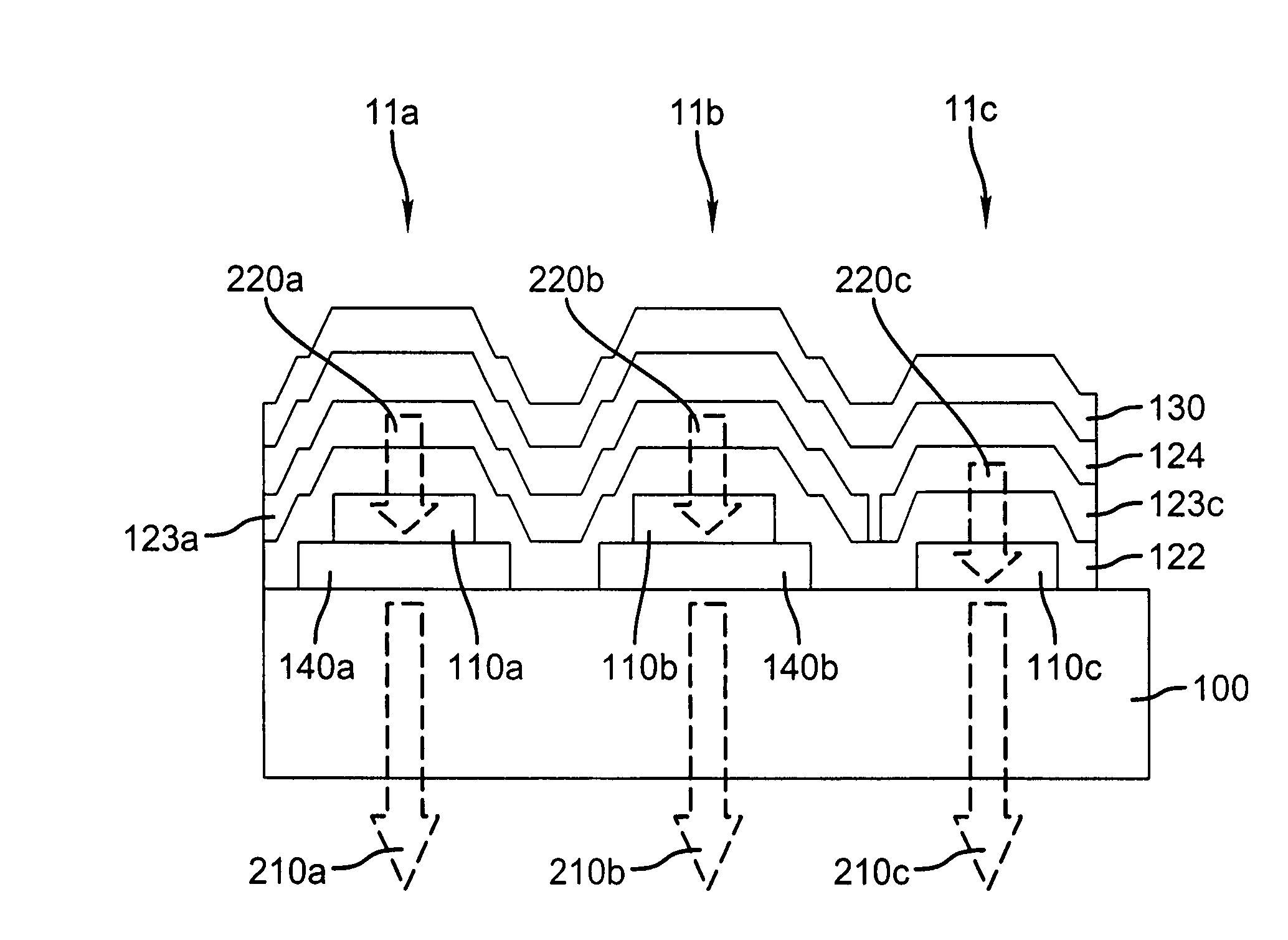
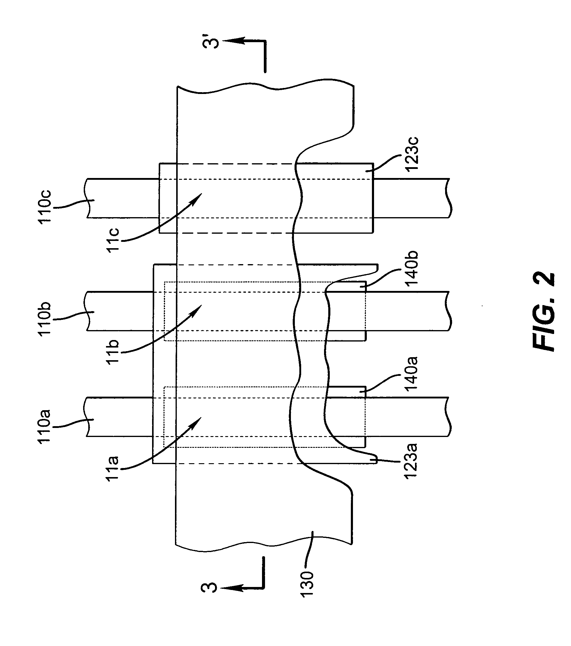
[0031]FIG. 2 shows a top side view of pixels 11a, 11b, and 11c according to the present invention. In a passive matrix configuration, these pixels can be addressed by providing a matrix of orthogonal electrodes such as first electrodes 110a, 110b, and 110c and second electrode 130. That is, pixel 11a is constructed from first electrode 110a and second electrode 130, pixel 11b is constructed from first electrode 110b and second electrode 130, and pixel 11c is constructed from first electrode 110c and second electrode 130. In this configuration, all pixels in a column share the same first electrode and all pixels in a row share the same second electrode. As such, these pixels are arranged into a stripe pattern. However, the present invention is not limited to this arrangement and other arrangements such as delta pattern arrangements and quad arrangements can be applied by one skilled in the art. Furthermore, the present invention is not limited to the passive matrix configuration and ...

second embodiment

[0045]FIG. 9 shows a top side view of pixels 11a, 11b, 11c, and 11d according to the present invention. The magenta light emitting layer 123a is provided for pixels 11a, 11b, and 11d to be common between these pixels, and therefore requires a precise alignment or patterning step. The green light emitting layer 123c is provided for pixels 11c and 11d, and requires a precise alignment or patterning step. In this manner, the number of precision aligned depositions required to form these four differently colored pixels is reduced from four to two. Light emitting layers 123a and 123c can be formed as previously described.

[0046] The combination of light emitting layers 123a and 123c in pixel 11d is arranged so as to produce light having broadband spectral components corresponding to the desired color of pixel 11d. The broadband emission is defined as a spectrum having emission throughout the visible wavelength range, and can be white in color. In order to achieve the red color desired for...


PUM


Abstract

It is an object of the present invention to avoid the above-mentioned problems and provide a multicolor OLED display with improved power efficiency that reduces the need for precisely patterning one or more of the OLED layers. This object is achieved by an OLED display having at least red, green, and blue colored pixels, including a magenta light emitting layer provided over a substrate for red and blue pixels and a green light emitting layer provided over the substrate for producing at least a green pixel. It is also achieved by first and second color filters in operative relationship with the magenta light-emitting layer to respectively produce red and blue pixels.

Description

CROSS REFERENCE TO RELATED APPLICATIONS [0001] This application claims priority from, and is a continuation-in-part of co-pending, commonly assigned U.S. patent application Ser. No. 11 / 113,484 filed Apr. 25, 2005 by Jeffrey P. Spindler, entitled “OLED Multicolor Displays”; and U.S. patent application Ser. No. 11 / 113,915 filed Apr. 25, 2005 by Jeffrey P. Spindler entitled “Multicolor OLED Displays”. [0002] Reference is made to commonly assigned U.S. patent application Ser. No. 11 / 050,162 filed Feb. 3, 2005 by Dustin L. Winters, et al., entitled “Making Multicolor OLED Displays”; and U.S. patent application Ser. No. 11 / 048,385 filed Feb. 1, 2005 by Michael E. Miller, et al., entitled “Color Display Device with Enhanced Pixel Pattern” the disclosures of which are incorporated by reference herein.FIELD OF INVENTION [0003] The present invention relates to organic light emitting diode (OLED) displays. More specifically, this invention relates to multicolor OLED displays having three or mo...

Claims


Application Information

Patent Timeline
Patent Type & Authority Applications(United States)
IPC IPC(8): H01J1/62H01J63/04
CPCC09K11/06H05B33/14C09K2211/1011C09K2211/1014C09K2211/1029C09K2211/1033C09K2211/1037C09K2211/1044C09K2211/107C09K2211/1088H01L27/3213H01L27/322H01L51/0021H01L51/0051H01L51/0052H01L51/0059H01L51/0062H01L51/0081H01L51/0094H01L51/5036C09K2211/1007H10K59/351H10K59/38H10K71/60H10K85/611H10K85/649H10K85/615H10K85/631H10K85/324H10K85/40H10K50/125
Inventor MILLER, MICHAEL E.SPINDLER, JEFFREY P.
Owner GLOBAL OLED TECH
Why Eureka
Try Eureka