Multi-protocol radio frequency identification transponder transceiver

a radio frequency identification and transceiver technology, applied in the direction of burglar alarm mechanical actuation, burglar alarm by hand-portable objects removal, instruments, etc., can solve the problems of complex rfid devices and limited amount of data that may be processed by existing rfid circuitry,

Active Publication Date: 2006-10-26
NXP USA INC
View PDF50 Cites 176 Cited by
  • Summary
  • Abstract
  • Description
  • Claims
  • Application Information

AI Technical Summary

Problems solved by technology

However, as more complex applications are sought for the RFID technology, the existing RFID circuitry is limited in the amount and type of data that may be processed.
If RFID devices are to be available for secure financial transactions or secure personal identification, more complex RFID devices may be needed to handle the type of data being transmitted.

Method used


Image

  • Multi-protocol radio frequency identification transponder transceiver
  • Multi-protocol radio frequency identification transponder transceiver
  • Multi-protocol radio frequency identification transponder transceiver

Examples


Embodiment Construction

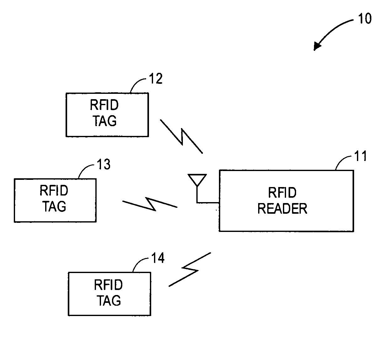
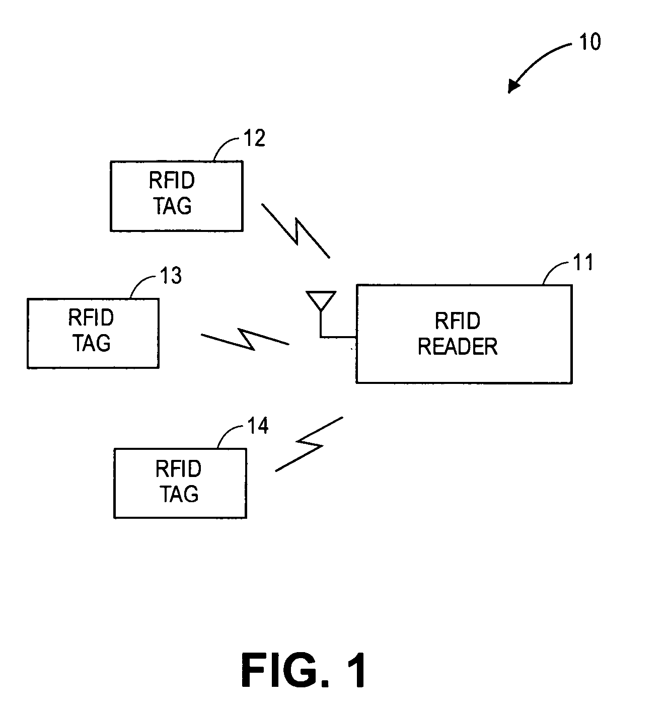
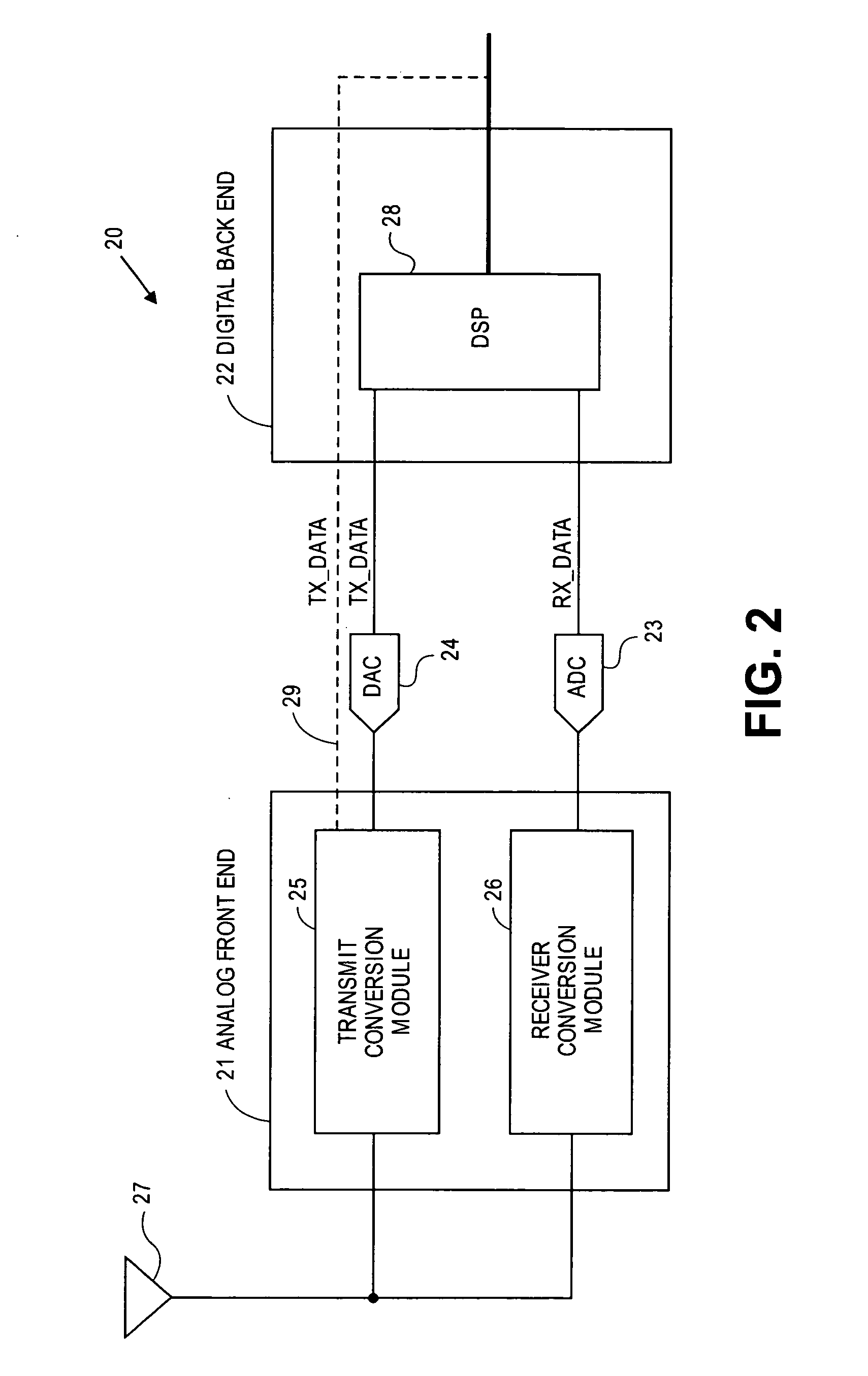
[0024] The embodiments of the present invention may be practiced in a variety of settings that implement a radio frequency identification (RFID) transceiver, either in a reader or in a tag, or in both. In one described embodiment, a RFID transceiver is implemented in a reader that incorporates an analog front end and a digital backend. One embodiment of the reader uses a down-conversion mixer, an analog-to-digital converter (ADC) and a digital-signal-processor (DSP). In another described embodiment, a RFID transceiver is implemented in a tag that also may incorporate an analog front end and digital processing. One embodiment of the tag uses pulse / level detection based on adaptive threshold control using a sample and hold circuit and an automatic gain control (AGC) circuit to adjust to the strength of the received signal. It is to be noted that the below described embodiments are just some of the embodiments available to practice the invention and that other embodiments may be readil...


PUM


Abstract

A transceiver for a RFID reader and a transceiver for a RFID transponder (tag) allow communication between the two devices. The RFID reader utilizes an analog front end and a digital backend. In the receiver portion of the transceiver, the front end of the RFID reader uses a pair of down-conversion mixers to demodulate a received signal into in-phase (I) and quadrature (Q) components and analog-to-digital converters (ADC) digitize the signal. A digital signal processor (DSP) in the back end processes the digital signal and uses a matched filter for data detection. The RFID tag receives an inductively coupled signal from the reader and the receiver portion of the tag uses a pulse / level detector that employs an analog comparator and a sample and hold circuit to detect the received signal. A digital decoder / controller is used to decode the incoming data and to establish a sampling clock for the pulse / level detector. An automatic gain control (AGC) circuit adjusts a receiver gain according to the received signal strength and controls tuning of magnetic coupling circuitry.

Description

CROSS REFERENCE TO RELATED APPLICATION [0001] This application claims the benefit of priority to U.S. Provisional Patent Application Ser. No. 60 / 655,175; filed Feb. 22, 2005; and titled “Multi-Protocol Radio Frequency Identification Transceivers,” which is incorporated herein by reference.BACKGROUND OF THE INVENTION [0002] 1. Technical Field of the Invention [0003] The embodiments of the invention relate to radio frequency identification (RFID) devices and more particularly to transceivers that are utilized in RFID readers and RFID transponders. [0004] 2. Description of Related Art [0005] Radio frequency identification (RFID) devices are being utilized in greater quantity in a multitude of applications. One of the more common areas for RFID implementation is in product identification, whether for inventory or for sale. The bar code scanner technology is slowly being replaced by RFID technology. In the simplest of applications, a passive RFID transponder, commonly called a tag or a c...

Claims


Application Information

Patent Timeline
Patent Type & Authority Applications(United States)
IPC IPC(8): H04Q5/22
CPCG06K7/0008H04B5/0031H04B5/0062
Inventor WU, JIANGFENGMAJOR, DONALD EDWARD
Owner NXP USA INC
Why Eureka
Try Eureka