System and method of tamper detection

a detection system and a technology of tampering detection, applied in the field of system and method of tamper detection, can solve the problems that the traditional mechanism of determining whether a product has been tampered with is often prone to human error, and achieve the effects of improving control over the handling of a sensitive product, facilitating rapid container integrity checking, and improving product safety

Active Publication Date: 2006-10-26
IBM CORP
View PDF17 Cites 33 Cited by
  • Summary
  • Abstract
  • Description
  • Claims
  • Application Information

AI Technical Summary

Benefits of technology

[0014] In particular, the present invention provides a means of improving control over the handling of a sensitive product by making it possible to remotely and automatically interrogate (without requiring visual inspection of) containers of the product to determine whether the containers have been tampered with. This facilitates rapid container integrity checking and leads to improved product safety because traditional mechanisms of determining whether a product has been tampered with are often prone to human error.

Problems solved by technology

This facilitates rapid container integrity checking and leads to improved product safety because traditional mechanisms of determining whether a product has been tampered with are often prone to human error.

Method used


Image

  • System and method of tamper detection
  • System and method of tamper detection
  • System and method of tamper detection

Examples


Embodiment Construction

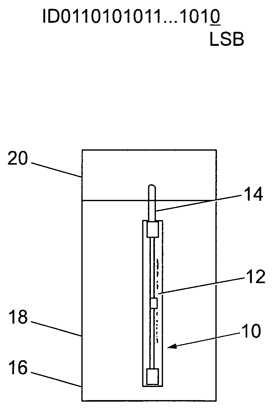
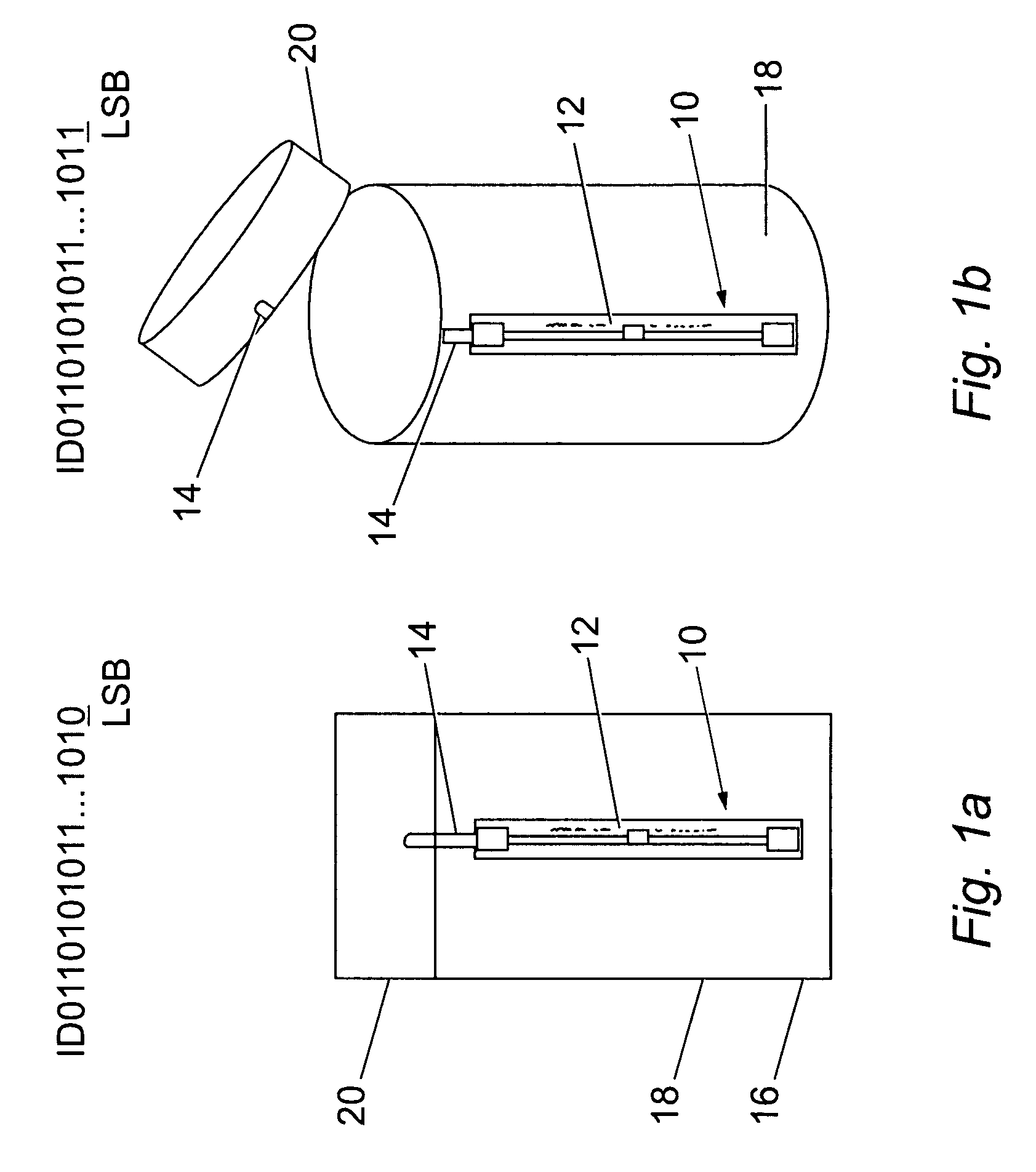
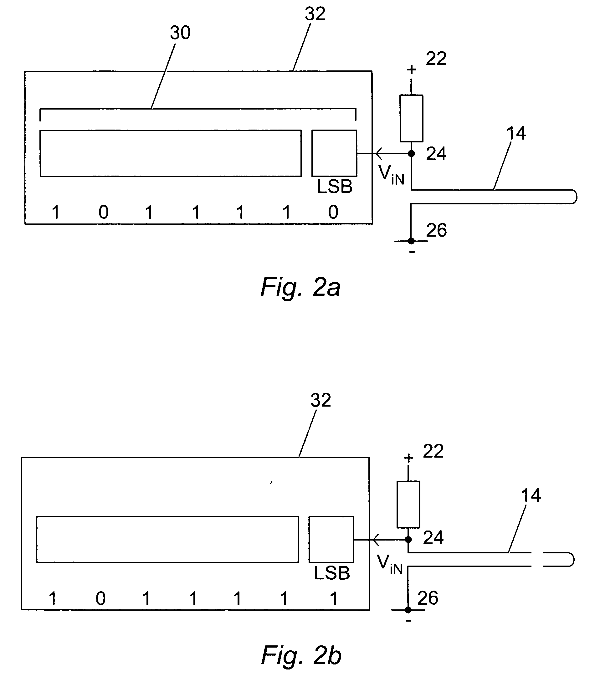
[0021] Referring to FIG. 1(a) the tamper detector 10 comprises an RFID tag 12 with a memory register and an external circuit in the form of a thin wire loop 14 coupled to the least significant bit (LSB) of the memory register. In use, the tamper detector 10 is attached to a container 16 comprising a first portion 18 being open at one end, and a cap 20 that is fittable over the open end of the first portion 18 to close the container 16.

[0022] The tamper detector 10 is attached to the container 16 in an arrangement in which the RFID tag 12 is stuck to (or embedded in) the first portion 18 and the thin wire loop 14 is attached to the cap 20. The thin wire loop 14 may be attached to the cap 20 by any of a variety of methods extending from simple adhesion with appropriate glue to inclusion of the thin wire loop 14 into a hole in the cap 20, which is then sealed using an epoxy-like cement. Referring to FIG. 1(b), with this arrangement, in the event of an attempt to tamper with the contai...


PUM


Abstract

The present invention relates to a system and method of tamper detection. A tamper detection system in accordance with an embodiment of the present invention includes: a passive electronic sensor including a circuit having first, second, and third nodes; a load connected between the first and second nodes of the circuit; a friable electrical connection element connected between the second and third nodes of the circuit; and a storage unit, connected to the second node of the circuit, for storing an identification code of the sensor; wherein in use a voltage is applied across the first and third nodes of the circuit, and when the friable electrical connection element is intact, the second node of the circuit is at a first voltage, and when the friable electrical connection element is broken, the second node of the circuit is at a second voltage.

Description

FIELD OF INVENTION [0001] The present invention relates to a system and method of tamper detection and in particular, to a system and method employing a radio frequency identification (RFID) tag. BACKGROUND ART [0002] Recent studies have shown that, at present, 80% of the pharmaceuticals being globally developed are biological products such as bio-therapeutic agents (e.g., vaccines) or biological supplies / samples (e.g., blood, serum etc.). These products typically cost ten times more than traditional products to handle during manufacture and transport through the supply chain. These additional costs arise because biological products are often sensitive to environmental conditions and thus require specialised handling. For instance, many biological products (e.g., enzymes) are temperature-sensitive and must be handled and stored at low temperatures. Similarly, other biological products are sensitive to the presence of oxygen or other ambient gases. Consequently, these products must b...

Claims


Application Information

Patent Timeline
Patent Type & Authority Applications(United States)
IPC IPC(8): G08B13/14
CPCB65D55/02B65D2401/00
Inventor COMMAGNAC, FRANCOISMESTRES, JEAN-CHRISTOPHEPICON, JOAQUINSECONDO, PIERRE
Owner IBM CORP
Why Eureka
Try Eureka