Image display apparatus and signal processing apparatus

a signal processing and image display technology, applied in image enhancement, image analysis, instruments, etc., can solve the problems of inability to display images in stereoscopic manner, redundant production of depth information for the elimination of hidden surfaces, etc., to improve the efficiency of image display apparatus, simple hardware and/or software configuration for synchronizing luminance and depth signals

Inactive Publication Date: 2006-10-26
BROTHER KOGYO KK
View PDF14 Cites 24 Cited by
  • Summary
  • Abstract
  • Description
  • Claims
  • Application Information

AI Technical Summary

Benefits of technology

[0028] In that, it is preferable that a hardware and / or software configuration for synchronizing those luminance and depth signals is simple, or requires no modification to an existing configuration or a few modifications, if any.
[0029] That is to say, it is also preferable from the perspective of improvements in the signal processing technique, to improve those image display apparatuses so as to allow the depth of a to-be-displayed object to be efficiently represented with a stereoscopic image.
[0030] In light of the circumstances described above, it is an object of the present invention to provide ones of techniques of displaying to a viewer an image stereoscopically representing a three-dimensional object to be displayed, which are novel techniques allowing the depth of a to-be-displayed object to be efficiently represented with a stereoscopic image.

Problems solved by technology

The reason is that, in this field of computer graphics, it is impossible to display an image in a stereoscopic manner.
Hence, in a case where the aforementioned image display apparatuses display images using the thus-formed image signal, there cannot conventionally be used again, the depth data which has been used in the aforementioned hidden surface elimination, requiring the depth data to be newly created.
As a result, conventionally, the depth information is redundantly produced for the hidden surface elimination and for the representation of the depth by the image display apparatuses.

Method used


Image

  • Image display apparatus and signal processing apparatus
  • Image display apparatus and signal processing apparatus
  • Image display apparatus and signal processing apparatus

Examples


first embodiment

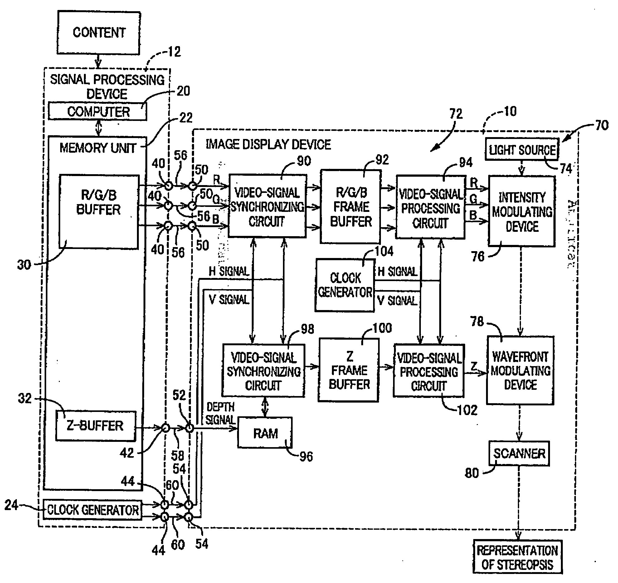
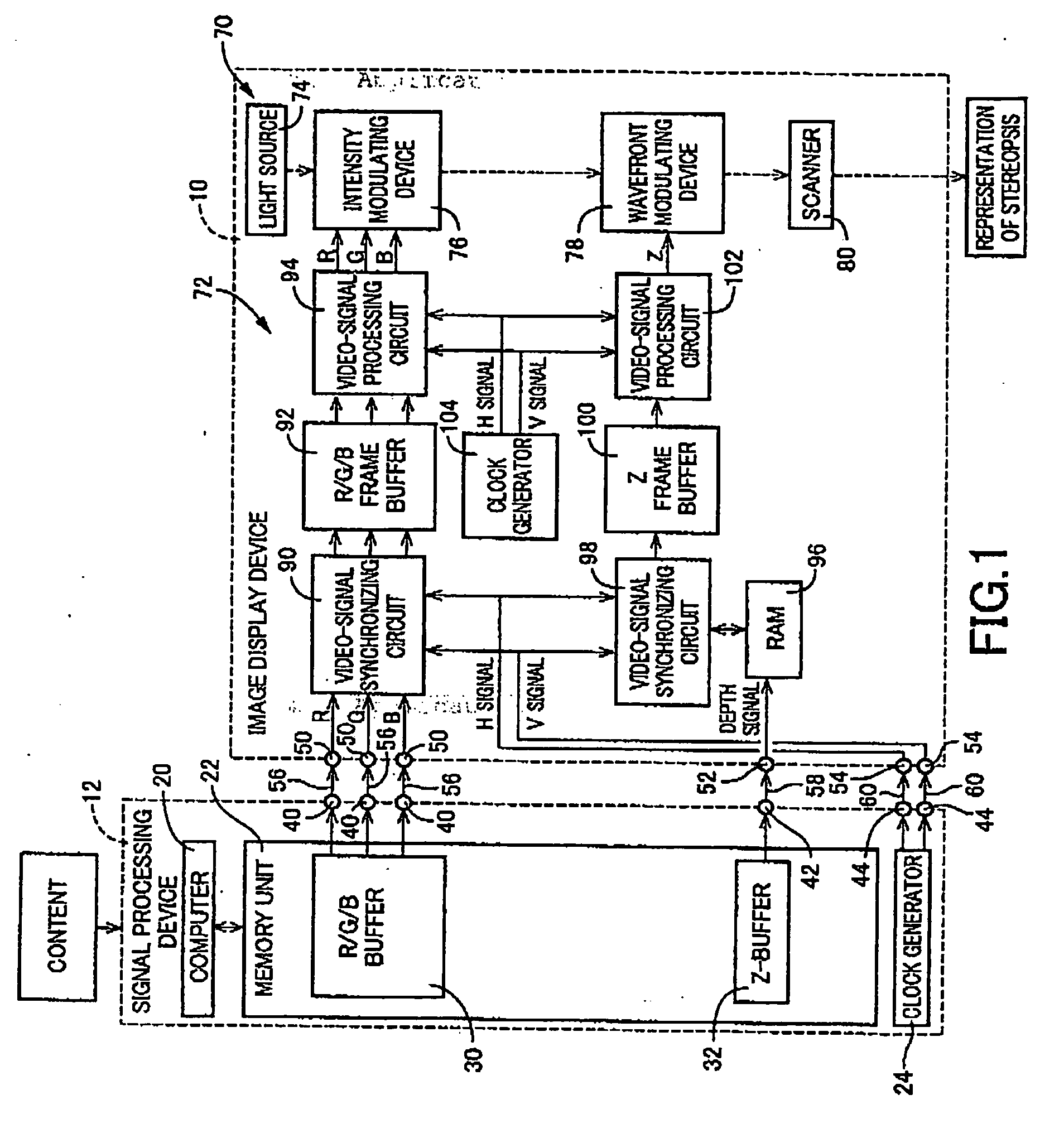
[0280] In FIG. 1, an image display device 10 of a retinal-scanning type according to the present invention is conceptually illustrated in block diagram. This image display device 10 is used in connection with a signal processing device 12 which is constructed to be physically separate from or integral with the image display device 10.

[0281] The image display device 10 projects a beam of light (this constitutes an example of the “light” set forth in the above mode (1)) on a retina of a viewer's eye, while scanning the beam of light, based on an RGB signal (this constitutes an example of the “luminance signal” set forth in the above mode (1)) and a depth signal both supplied from the signal processing device 12, to thereby display to the viewer an image stereoscopically representing a three-dimensional object to be displayed. That is to say, this image display device 10 is classified as, what is called, a retinal scanning display.

[0282] An RGB signal is typically a signal formed by c...

third embodiment

[0369] In the third embodiment, as illustrated in FIG. 8, the signal processing device 152 generates an image signal formed by combining luminance and depth signals, and outputs the generated image signal to the image display device 150. As a result, the image display device 150 displays a stereoscopic image based on the image signal.

[0370] In contrast, in the present embodiment, as illustrated in FIG. 14, a signal processing device 220 is used instead of the signal processing device 152. However, the signal processing device 220 includes, similarly with the signal processing device 152, the computer 20, the memory unit 22, and the depth-signal embedding circuit 156. In the signal processing device 220, the depth-signal embedding circuit 156 embeds a depth signal into a luminance signal according to the procedure similar with the third embodiment, resulting in the generation of an image signal in the form of a composite signal.

[0371] As illustrated in FIG. 14, the signal processing...

sixth embodiment

[0439] In the sixth embodiment, as illustrated in FIG. 18, on an upstream side of each line-by-line storage region 344, the image-signal storage sub-region 350 is located, while, on its downstream side, the control-signal storage sub-region 352 is located.

[0440] Alternatively, in the present embodiment, as illustrated in FIG. 19, on a downstream side of each line-by-line storage region 344, the image-signal storage sub-region 350 is located, while, on its upstream side, the control-signal storage sub-region 352 is located.

[0441] Owing to the employment of such an organization, the present embodiment would facilitate the storage of a control signal into the RAM 314 prior to that of an image signal, per scan-line, and the retrieval of a control signal from the RAM 314 prior to that of an image signal, per scan-line, and the transmission of a control signal prior to that of an image signal.

[0442] Next, an eighth embodiment of the present invention will be described, provided that, be...


PUM


Abstract

An apparatus is disclosed for displaying to a viewer an image stereoscopically representing a three-dimensional object to be displayed. The apparatus includes: an emitter emitting light, having an intensity modulating section capable of intensity modulation for modulating an intensity of the light emitted from the emitter; a wavefront-curvature modulator capable of wavefront-curvature modulation for modulating a curvature of wavefront of the light emitted from the emitter; and a controller controlling the intensity modulation and the wavefront-curvature modulation, based on a luminance signal indicative of luminance of the image, and a depth signal indicative of depth of the image. The depth signal is a signal corresponding to depth data produced in a rendering process for the object to be displayed.

Description

CROSS-REFERENCE TO RELATED APPLICATIONS [0001] This application is based on Japanese Patent Applications No. 2003-429342 filed Dec. 25, 2003, and No. 2004-077977 filed Mar. 18, 2004, and PCT International Application No. PCT / JP2004 / 019055 filed Dec. 21, 2004, the contents of which are incorporated hereinto by reference. [0002] This application is a continuation of PCT International Application No. PCT / JP2004 / 019055 filed Dec. 21, 2004, which was published in Japanese under PCT Article 21(2).BACKGROUND OF THE INVENTION [0003] 1. Field of the Invention [0004] The invention relates to techniques of displaying images, and more particularly to techniques of processing signals related to a display operation of images. [0005] 2. Description of the Related Art [0006] There are known as techniques of displaying images, image display apparatuses for displaying to a viewer an image stereoscopically representing a three-dimensional object to be displayed. [0007] One example of such image displa...

Claims


Application Information

Patent Timeline
Patent Type & Authority Applications(United States)
IPC IPC(8): H04N13/02G02B27/02G06T15/40H04N13/363
CPCG06T15/405G06T2207/10012H04N13/0003H04N13/0022H04N2213/003H04N13/0059H04N13/0422H04N13/044H04N13/0459H04N13/0048H04N13/344H04N13/194H04N13/324H04N13/161H04N13/363H04N13/10H04N13/128
Inventor TAKAYAMA, HARUHISASAKAUE, OSAMUHIBINO, YOSHIHIKO
Owner BROTHER KOGYO KK
Why Eureka
Try Eureka