Display device, terminal device, light source device, and optical member
- Summary
- Abstract
- Description
- Claims
- Application Information
AI Technical Summary
Benefits of technology
Problems solved by technology
Method used
Image
Examples
first embodiment
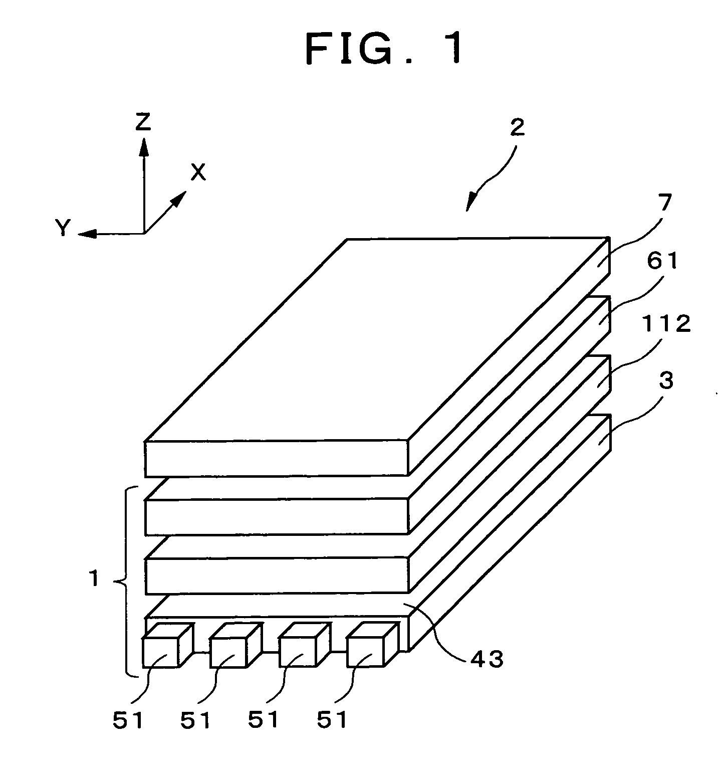
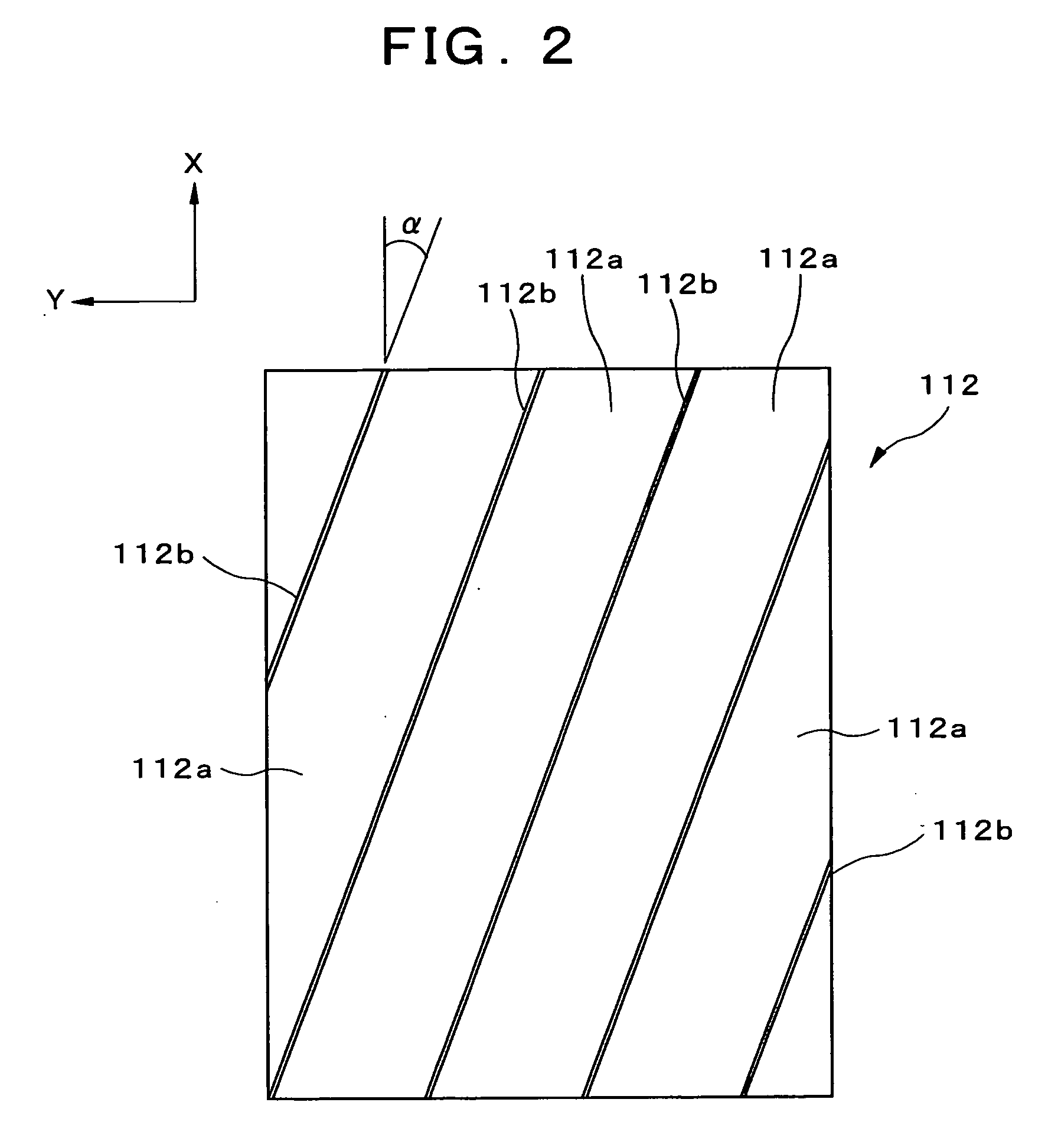
[0067] The display device, terminal device, light source device, and optical member according to embodiments of the present invention will be described in detail hereinafter with reference to the accompanying drawings. The display device, terminal device, light source device, and optical member according to the present invention will first be described. FIG. 1 is a perspective view showing the display device according to the present embodiment; FIG. 2 is a top view showing a louver as the light-direction restricting element of the display device shown in FIG. 1; FIG. 3 is a top view showing the anisotropic scattering sheet of the display device shown in FIG. 1; FIG. 4 is a top view showing the relationship between the light-restricting direction of the louver and the scattering direction of an anisotropic diffusion sheet; and FIG. 5 is a perspective view showing the terminal device according to the present embodiment.
[0068] As shown in FIG. 1, a light source device 1 is provided in ...
second embodiment
[0111] Furthermore, in the same manner as in the aforementioned second embodiment, the thickness of the display device can be reduced since the anisotropic scattering sheet is not provided in the present embodiment. Furthermore, the anisotropic scattering unit, the louver, and the transmissive liquid crystal panel are optically bonded. Therefore, interference fringes from air layers can be prevented from occurring, and the display quality can be enhanced even further. The louver is also provided on the user side of the display panel, and anisotropic scattering structures are formed in this louver. The user can therefore easily attach and detach a louver equipped with an anisotropic scattering structure according to the situation.
[0112] A fourth embodiment of the present invention will next be described. FIG. 15 is a perspective view showing the display device according to the present embodiment; and FIG. 16 is a perspective view showing the anisotropic scattering sheet of the displa...
fourth embodiment
[0115] An example was described in the fourth embodiment and modification thereof in which a prism sheet or lenticular lens is provided separately from the louver, but the one-dimensionally arranged prism structures 641 may be formed directly on the surface of the louver, and the cylindrical lenses 651 may also be formed directly on the surface of the louver.
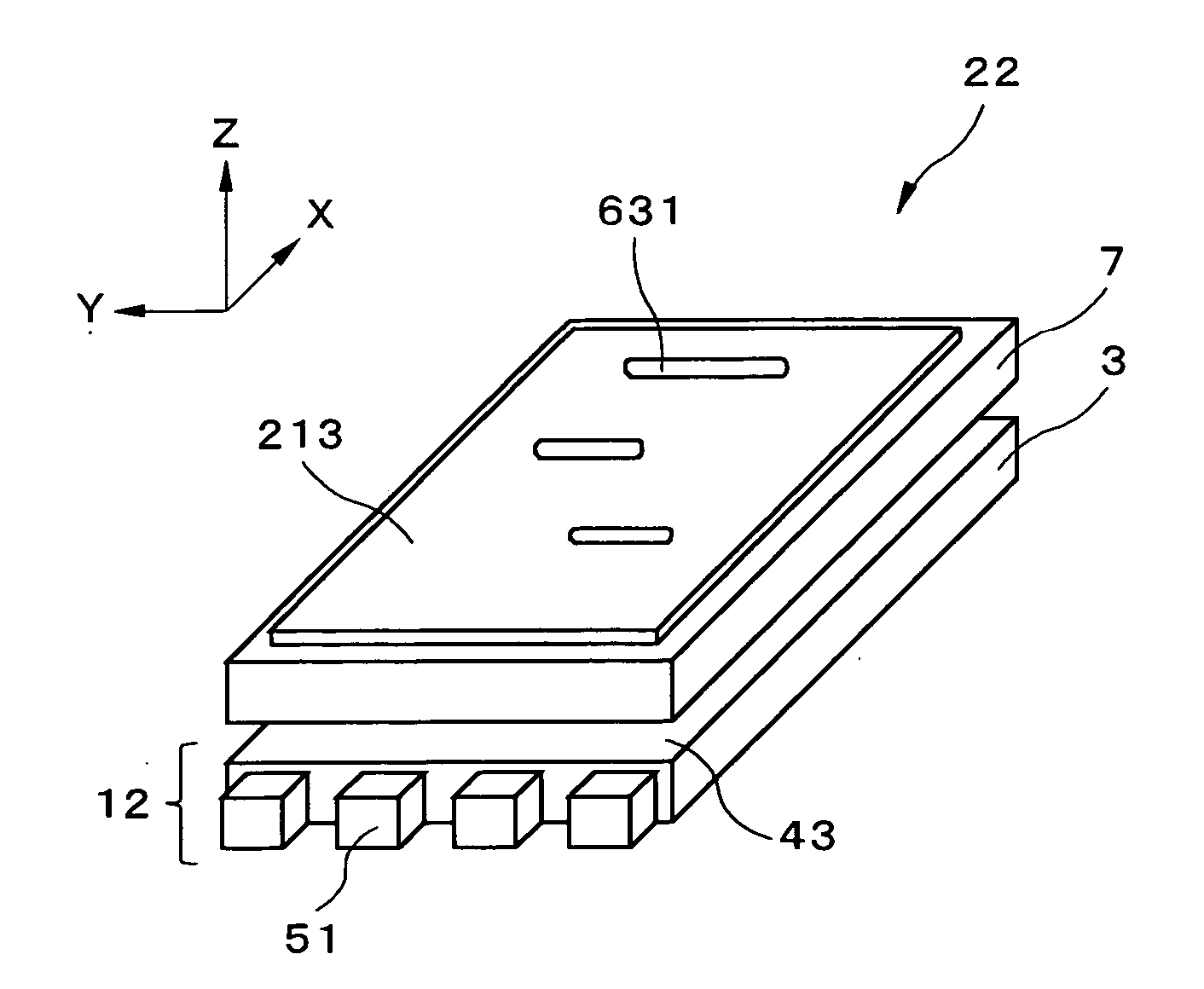
[0116] A fifth embodiment of the present invention will next be described. FIG. 18 is a sectional view showing the display device according to the present embodiment; and FIG. 19 is a sectional view showing the transparent / scattering state switching element in the display device shown in FIG. 18. As shown in FIG. 18, the display device 24 of the present embodiment differs from that of the first embodiment in that a transparent / scattering state switching element 122 is provided between the anisotropic scattering sheet 61 and the transmissive liquid crystal panel 7. Through the switching operation of the transparent / scattering sta...
PUM
 Abstract
Description
Claims
Application Information
 - R&D
- Intellectual Property
- Life Sciences
- Materials
- Tech Scout
- Unparalleled Data Quality
- Higher Quality Content
- 60% Fewer Hallucinations
Browse by: Latest US Patents, China's latest patents, Technical Efficacy Thesaurus, Application Domain, Technology Topic, Popular Technical Reports.
© 2025 PatSnap. All rights reserved.Legal|Privacy policy|Modern Slavery Act Transparency Statement|Sitemap|About US| Contact US: help@patsnap.com


