Nickel alloy composition

Inactive Publication Date: 2006-10-26
ROLLS ROYCE PLC
View PDF40 Cites 20 Cited by
  • Summary
  • Abstract
  • Description
  • Claims
  • Application Information

AI Technical Summary

Benefits of technology

[0018] The laser cladding process is particularly shape-faithful, making available shaping accuracies of +/−0.04 mm in the laying down of the alloy of the present invention. Where the confi

Problems solved by technology

These elements are found generally to harm the resistance

Method used


Image

  • Nickel alloy composition
  • Nickel alloy composition
  • Nickel alloy composition

Examples


Example

DETAILED DESCRIPTION OF THE DRAWINGS

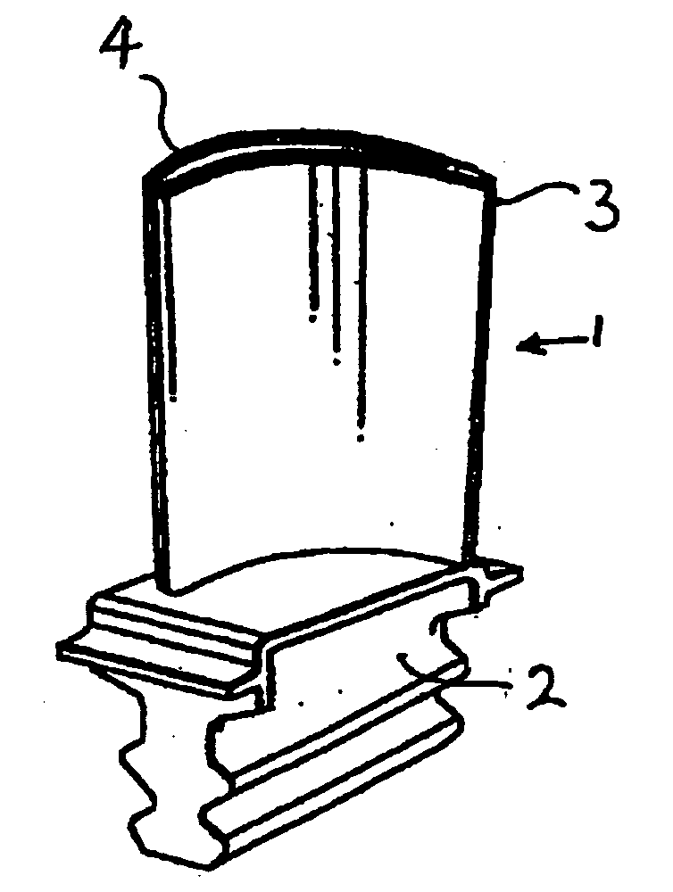
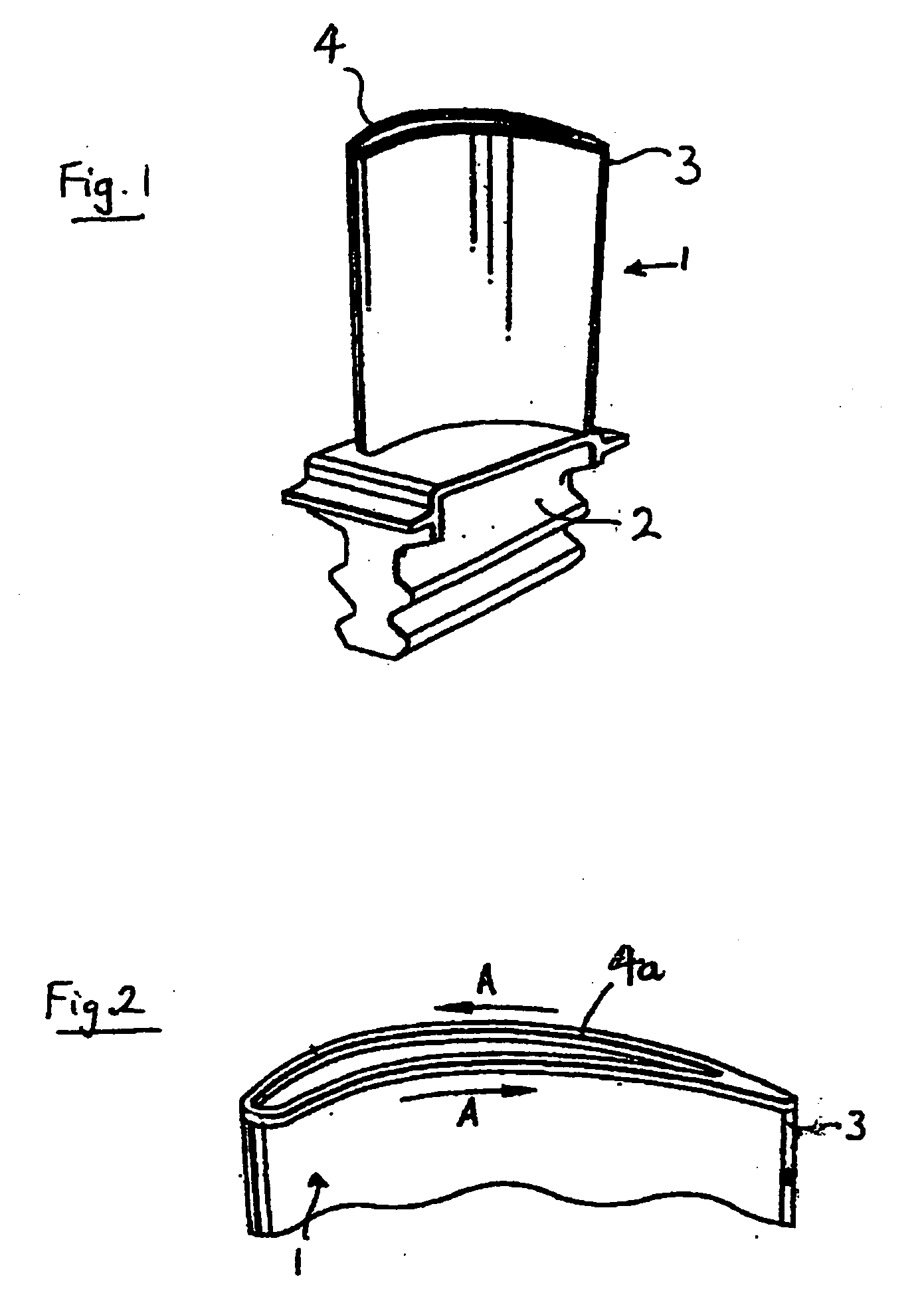
[0028] Referring to the drawings, in which like parts are designated alike, a turbine blade 1 of a gas turbine propulsion engine has a geometry which is generally conventional in the art. The blade 1 has a root 2 and a tip 3, the tip 3 being provided with a squealer comprising a peripheral wall 4. The squealer serves in operation to enclose a body of relatively cool air at the tip of the blade in the tip well bounded by the wall 4. Holes (not shown) in the tip of the blade provide for air flow communication between hollow chambers within the blade and the said body of relatively cool air.

[0029] The blade is preferably formed from a suitable high temperature material, such as an appropriate nickel-based superalloy of a type known in the art, and may be cast as single crystal or directionally solidified casting to promote the high temperature properties of the blade 1.

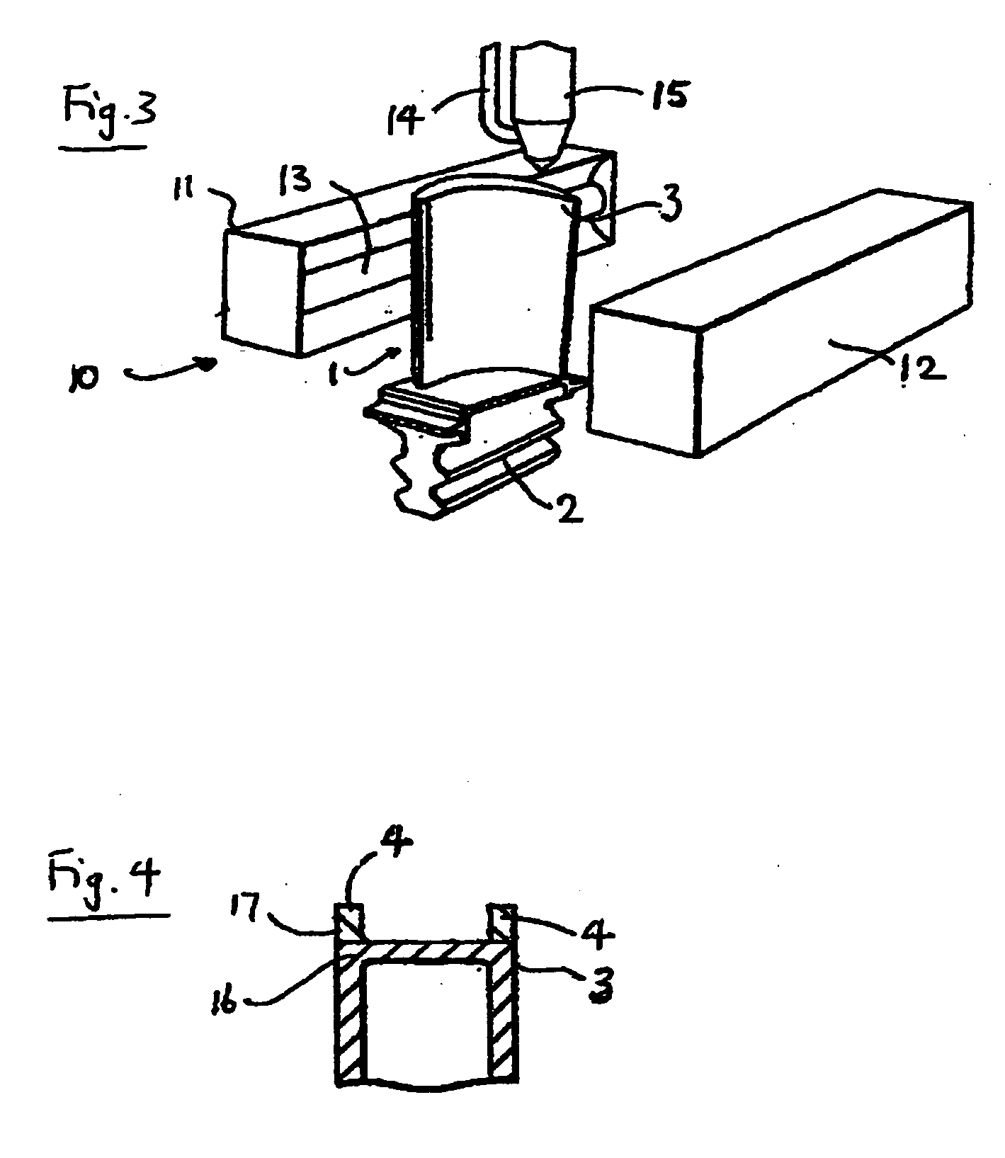
[0030] The wall 4 of the squealer tip is formed using the novel nickel alloy co...


PUM

PropertyMeasurementUnit
Compositionaaaaaaaaaa
Depthaaaaaaaaaa

Abstract

A nickel alloy composition, having particular utility for forming an oxidation resistant blade tip on a turbine blade, preferably has a composition substantially as defined by the nominal composition Cr 4.5 wt %; Al 6 wt %; Co 4 wt %; Ta 6 wt %; Re 4 wt %; Hf 0.15 wt %; C 0.05 wt %; Si 0.1 wt %; B 0.005 wt %; W 2 wt %; La 0.003-0.005 wt %; and Y 0.003 to 0.005 wt %; the remainder being nickel.

Description

FIELD OF THE INVENTION [0001] The present invention relates to a nickel alloy composition. In particular, the invention relates to a nickel alloy composition for application to the tips of gas turbine blades to act as an oxidation and corrosion resistant barrier. BACKGROUND OF THE INVENTION [0002] U.S. Pat. No. 5,622,638 (Schell et al; 22 Apr. 1997), the disclosure of which is incorporated herein by reference, describes a nickel-based alloy composition for application to the tips of gas turbine blades (which are conventionally formed from a nickel-based superalloy) to act as an oxidation and corrosion resistant barrier, most particularly a high temperature oxidation and corrosion resistant barrier. The nickel-based alloy composition consists essentially of about 14 to about 18 wt % Cr, about 6.45 to about 6.95 wt % Al, about 9.75 to about 11.45 wt % Co, about 5.95 to about 6.55 wt % Ta, about 1.85 to about 2.35 wt % Re, about 0.05 to about 1.75 wt % Hf, about 0.006 to about 0.03 wt ...

Claims


Application Information

Patent Timeline
IPC IPC(8): C22C19/05B23K35/30B23P6/00F01D5/20F01D5/28
CPCB23K35/304B23P6/007F01D5/28C22C19/058F01D5/20C22C19/057
Inventor SHIPTON, MARK H.BROOMFIELD, ROBERT W.
Owner ROLLS ROYCE PLC
Why Eureka
Try Eureka