Acid gas pretreating method

a technology of acid gas and pretreatment method, which is applied in the direction of gaseous fuel, separation process, lighting and heating apparatus, etc., can solve the problems of difficult to exploit solid sulfur, no longer economically advantageous conventional treatment, and requiring several recompression stages, so as to reduce the proportion of acid compounds, reduce the cost, and reduce the effect of acid compound proportion

Inactive Publication Date: 2006-10-26
INST FR DU PETROLE +1
View PDF4 Cites 39 Cited by
  • Summary
  • Abstract
  • Description
  • Claims
  • Application Information

AI Technical Summary

Benefits of technology

[0029] In this case, the present invention allows to significantly limit the proportion of acid compounds sent onshore with the associated gas by performing a pretreatment of this associated gas on the platform prior to sending it onshore for a finishing treatment. Furthermore, pretreatment of the gas consequently allows to

Problems solved by technology

These methods have the drawback of producing gaseous H2S at low pressure, thus requiring several recompression stages for reinjection into the reservoir.
When the associated gas contains more than 10% by mole of H2S, conventional treatments are no longer economically adv

Method used


Image

  • Acid gas pretreating method
  • Acid gas pretreating method
  • Acid gas pretreating method

Examples


Embodiment Construction

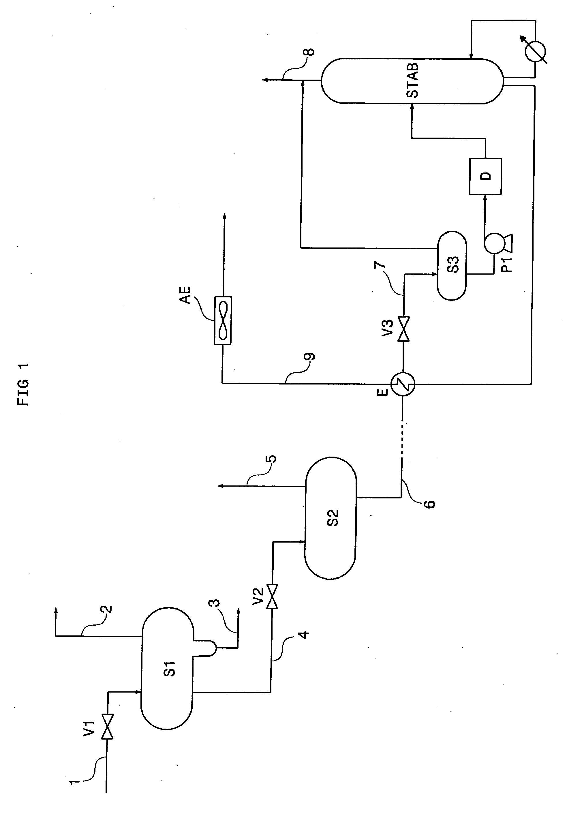
[0034] In FIG. 1, the crude petroleum effluent produced at the wellhead flows in through line 1. This effluent is expanded by expansion means V1, then fed into separation device S1. Expansion means V1 can be a valve or a combination of valves. Expansion allows to release in gaseous form the light hydrocarbons and acid compounds such as H2S, CO2, COS and mercaptans. Device S1 works at high pressure typically ranging between 40 and 120 bar absolute. It allows separation into three phases: associated gas, oil and water. At the top of separator S1, a high-pressure associated gas is recovered through line 2. The water is discharged from separator S1 through line 3.

[0035] The oil separated in device S1 is discharged through line 4, expanded by expansion means V2 and fed into separation device S2 operating at medium pressure, typically between 10 and 60 bar absolute. In device S2, a medium-pressure gas and a liquid effluent are separated and discharged through lines 5 and 6 respectively. ...


PUM

PropertyMeasurementUnit
Temperatureaaaaaaaaaa

Abstract

The method allows pretreatment of an acid gas that can comprise more than 10% H2S, for example a natural gas or a gas associated with the production of a crude petroleum effluent.
The gas is dehydrated in unit DH, then cooled by heat exchangers E9 to E12 and by expansion carried out through valve V7. Cooling allows part of the H2S contained in the gas to be condensed. The condensates are separated from the gas in drum B1.
The liquid recovered at the bottom of drum B1 is pumped and injected into well P to be sequestered in an underground reservoir or a geologic structure. The gas discharged at the top of drum B1 is depleted in H2S. This gas is sent through line 43 to a treating site in order to be subjected to additional treatments prior to being used.

Description

FIELD OF THE INVENTION [0001] The invention relates to a method for pretreating an acid gas, i.e. a gas containing high proportions of acid compounds, notably hydrogen sulfide (H2S), carbon dioxide (CO2), carbon oxysulfide (COS) and mercaptans. [0002] The present invention can be used for treating a natural gas or a gas associated with a petroleum effluent produced on the site of an oil reservoir, in particular sites that are not very accessible or offshore platforms. [0003] When the production of oil reservoirs is started, the crude petroleum effluent is roughly stabilized, i.e. separated from its associated gas, prior to undergoing an additional finishing treatment in order to be marketed. [0004] In this type of production, the associated gas, when it contains high proportions of acid gases, notably H2S (typically more than 10% by mole H2S), is generally difficult to exploit and can be partly reinjected on the production site into an injection well. [0005] The present invention is...

Claims


Application Information

Patent Timeline
IPC IPC(8): B01D53/46
CPCB01D53/002F25J2270/12B01D53/26C10L3/102C10L3/106F25J3/0209F25J3/0233F25J3/0242F25J3/061F25J3/0635F25J3/0645F25J2200/02F25J2220/60F25J2220/66F25J2235/60F25J2240/02F25J2240/40B01D53/1462F25J3/0266F25J3/067Y02C20/40
Inventor LALLEMAND, FRANCOISLECOMTE, FABRICELEMAIRE, ERICRENAUD, XAVIER
Owner INST FR DU PETROLE
Why Eureka
Try Eureka