
Flow cell and a reactor for reactions between fixed reacting substances and liquid reacting substances, and a method for operating the reactor

a technology of fixed reacting substances and flow cells, which is applied in the field of flow cells and reactors for reacting substances with fixed reacting substances and liquid reacting substances, can solve the problems of affecting the effect of the reaction, the reaction takes a relatively long time, and the reaction is not sufficiently complex, so as to reduce the number of pumps and reduce the cost , the effect of saving spa

Inactive Publication Date: 2006-10-26
MORITEX CORP
View PDF0 Cites 17 Cited by
  • Summary
  • Abstract
  • Description
  • Claims
  • Application Information

AI Technical Summary

Benefits of technology

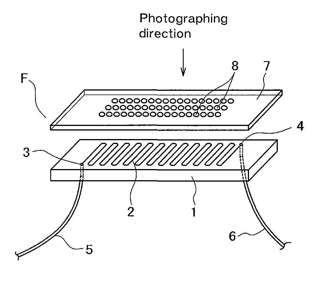
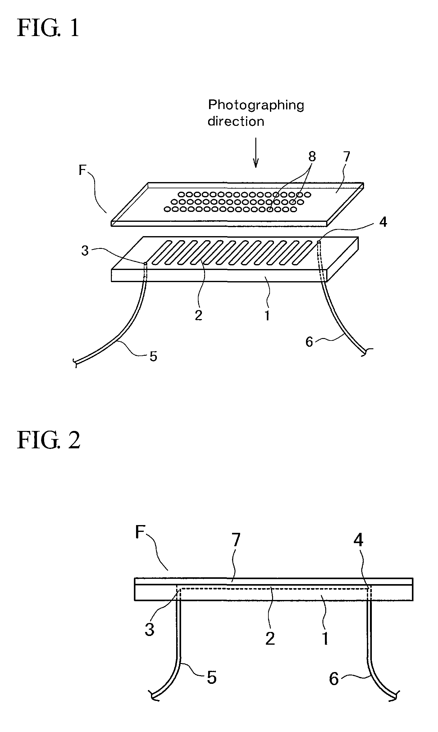
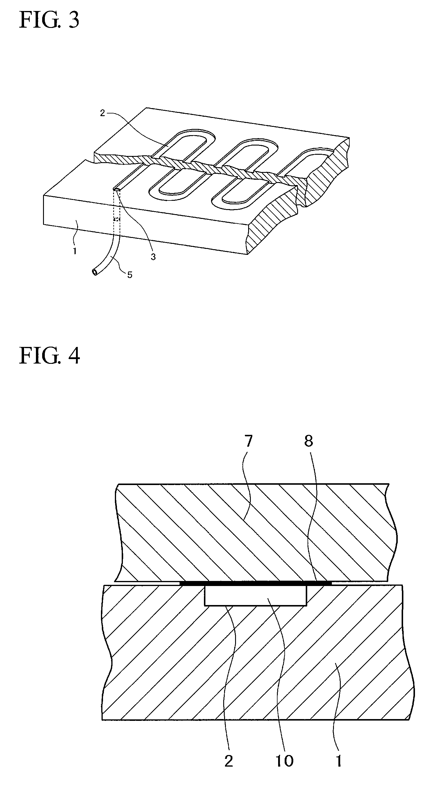
[0026] In the flow cell of this invention, the passage for letting fixed reacting substances and any one of liquid reacting substances react with each other can be established when the first plate having a continuous groove formed, for example, in zigzag and the second plate are kept in contact with each other for supporting each other. Therefore, fixable reacting substances can be easily fixed at plural places corresponding to the continuous groove while the plates are disconnected from each other, and the reactions between the liquid reacting substance flowing in the common passage and the plural fixed reacting substances can be performed efficiently. Furthermore, the luminescences generated by the reactions can be detected by a digital camera through the light transmitting first or second plate.
[0027] The liquid reacting substance flowing in the passage is kept in the passage established by the continuous groove and the plate surface and does not spread. So, if air is made to intervene between the liquid reacting substance and the system liquid when the liquid reacting substance is moved by using the system liquid, the interfaces consisting of liquid-air-liquid are maintained also in the passage. Therefore, the contamination between liquids can be reliably prevented.
[0030] Therefore, the number of pumps can be minimized to lower the cost and to save the space.

Problems solved by technology

However, the above-mentioned conventional techniques have the following problems.
First, the conventional CLEIA and FIA have a problem that it takes a relatively long time for sufficiently performing the antigen-antibody reactions.
Furthermore, the conventional technique described in said non patent document has a problem that since the reactions with a sample and an enzyme-labeled antibody must be performed in a separate process, the working efficiency is low.
However, since the inner form of the flow cell is rhombic, the liquid is likely to spread, and mixing of liquids (contamination) is feared.
However, since the inner form of the flow cell is rhombic, air is likely to deformed, and there also remains a fear of contamination.
Moreover, the conventional technique has a problem that since the number of pumps is large the equipment is expensive and large.
Next, the conventional technique described in said patent document 1 has problems that since capillarity is used for liquid injection and discharge, the system is open, and therefore that automation is difficult and that the flow velocity of injection and discharge cannot be controlled.
Furthermore, the conventional technique described in said patent document 2 has problems that a large amount of a labeled antibody is necessary since it is necessary to perform the reaction between a sample and the labeled antibody beforehand, and that since the reaction site is small, the number of reactions detectable at a time is limited.

Method used


Image

  • Flow cell and a reactor for reactions between fixed reacting substances and liquid reacting substances, and a method for operating the reactor
  • Flow cell and a reactor for reactions between fixed reacting substances and liquid reacting substances, and a method for operating the reactor
  • Flow cell and a reactor for reactions between fixed reacting substances and liquid reacting substances, and a method for operating the reactor

Examples


example 1

[0091] A particular embodiment of the flow cell and the reactor of this invention, and a particular example of the antigen-antibody reactions performed using them are described below.

[0092] As the second plate 7 used as a component of the flow cell F, a light transmitting acrylic plate was used. As the first plate 1, a chip made of polydimethylsiloxane (PDMS) was used, and a zigzag continuous groove 2 with a groove width of 1 mm and a groove depth of 0.2 mm was formed in it. The first plate 1 and the second plate 7 were kept in contact with each other to form a flow cell. In this case, the inner capacity of the passage 10 was 75 μL.

[0093] On the other hand, antigens were fixed on the acrylic plate used as the second plate 7 by an optical fixing method.

[0094] The first plate 1 and the second plate 7 were not made to adhere to each other, but aluminum blocks as first and second plates as shown in FIG. 7 were used for contact bonding. A heater was installed on the aluminum block use...


PUM


Abstract

A flow cell having a first plate having a continuous groove formed as a passage on one surface of the plate and having gas / liquid inlet / outlet portions at both the ends of the continuous groove, and a second plate to be kept in contact with said one surface of the first plate, wherein at least either of the first and second plates allows light transmission; fixable reacting substances are fixed on the surface of the second plate, to be kept in contact with the first plate, at plural places corresponding to the continuous groove; and the first and second plates are kept in contact with each other to support each other, for establishing the passage of any one of liquid reacting substances common to the plural fixed reacting substances.

Description

INCORPORATION BY REFERENCE [0001] The present application claims priority under 35 U.S.C. §119 to Japanese Patent Application No. 2005-128632 filed on Apr. 26, 2005. The content of the application is incorporated herein by reference in its entirety. FIELD OF THE INVENTION [0002] The present invention relates to a flow cell and a reactor for reactions between fixed reacting substances and liquid reacting substances such as antigen-antibody reactions, and a method for operating the reactor. BACKGROUND OF THE INVENTION [0003] Conventional techniques developed for measuring the amount of a test substance in a sample include immunoassay using antigen-antibody reactions. [0004] One of immunoassay techniques is enzyme immunoassay (EIA) in which antigen-antibody reactions are traced using enzyme activity as a label, for determining the amount of an antigen or antibody based on the result. The EIA methods include chemiluminescent enzyme immunoassay (CLEIA) using chemiluminescence, and fluore...

Claims


Application Information

Patent Timeline
IPC IPC(8): C12M3/00
CPCB01L3/502715B01L3/50273B01L3/502738B01L2200/027G01N2021/0325B01L2300/0816B01L2300/0877B01L2400/0487B01L2300/0636
Inventor TOMIDA, MAIKOMYOGADANI, TORU
Owner MORITEX CORP
Learn More