High performance constant velocity universal joint

a constant velocity, universal joint technology, applied in the direction of yielding couplings, shafts and bearings, rotary machine parts, etc., can solve the problems of joint failure, less desirable, rotational velocity oscillation of a conventional cardan joint, etc., and achieve the effect of reliable primary seal

Active Publication Date: 2006-10-26
AIRCRAFT GEAR CORP +1
View PDF73 Cites 19 Cited by
  • Summary
  • Abstract
  • Description
  • Claims
  • Application Information

AI Technical Summary

Benefits of technology

[0009] In view of the foregoing, it is a general object of the present invention to adapt the constant velocity joint to a more hostile environment by providing a more reliable primary seal than has heretofore been provided.

Problems solved by technology

Constant velocity joints are used in numerous vehicular applications where the rotational velocity oscillation of a conventional cardan joint is unacceptable.
However, in environmentally unfriendly applications they are less desirable because of the problems of keeping dirt and debris out of the joint.
However, as has become apparent to some motorists, once the boot tears, debris and moisture can enter the joint because the boot itself is the primary seal.
Thus, when the boot tears, it is not long thereafter, without attention, that the joint will fail.
Although it is desirable to use constant velocity joints in more environmentally demanding applications, the inability of the seal to withstand tough environmental conditions is a strong negative factor.
In off the road heavy machinery applications, not only is there a substantial danger of tearing the boot during a relatively short period of operation, but almost a guarantee of enough debris to cause the joint to fail shortly after it has torn.
But again, there is also the possibility of likelihood of tearing the rubber boot with almost certain failure of the joint to follow, particularly when running through sand, water, and the like.
However, these are typically characterized as complex, often formed of multiple parts, requiring springs or the like to keep them in operation, and having relatively limited flexing capability, well short of the 40 degree flexing capability demanded in some off road applications.

Method used


Image

  • High performance constant velocity universal joint
  • High performance constant velocity universal joint
  • High performance constant velocity universal joint

Examples


Embodiment Construction

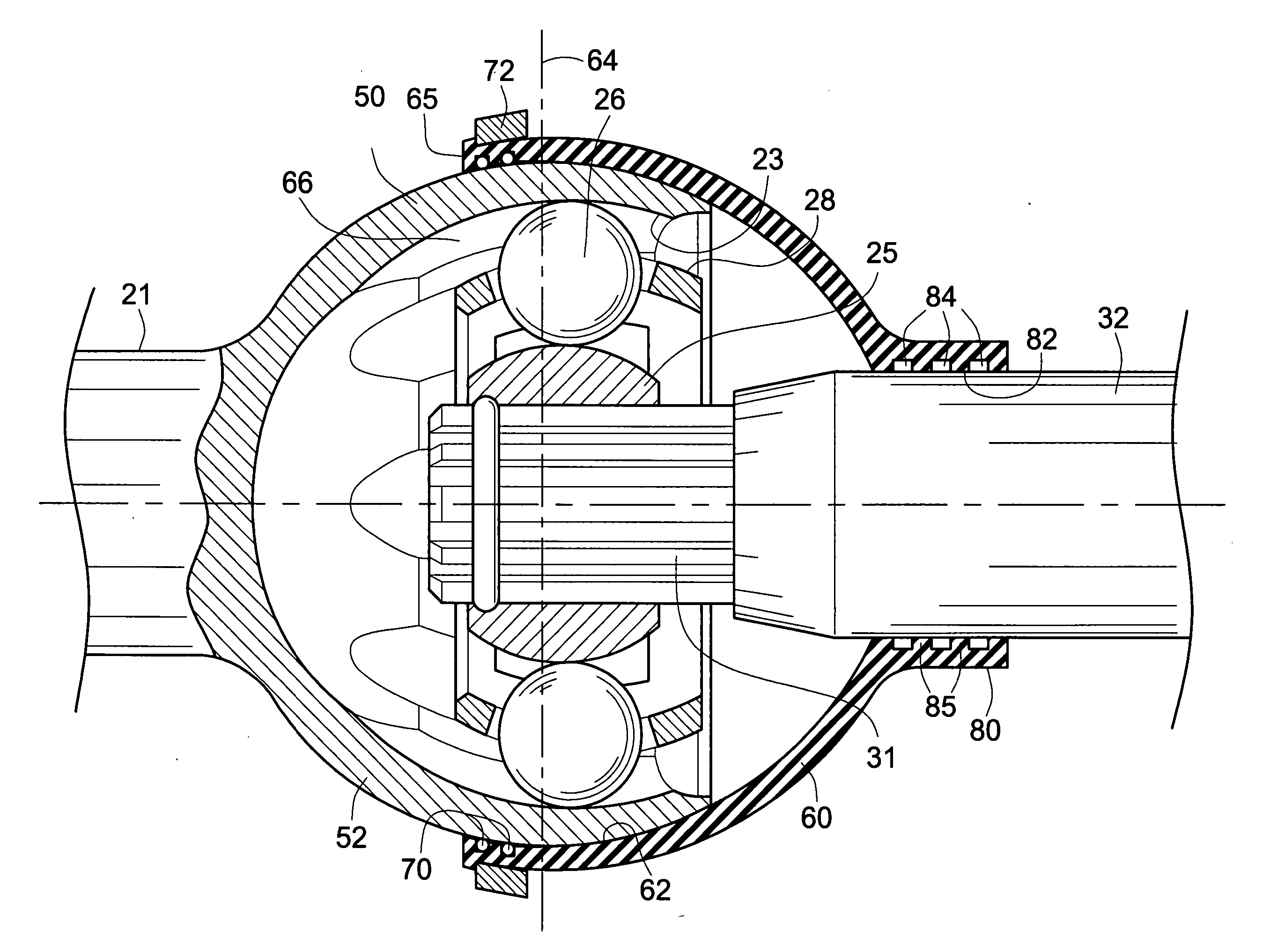
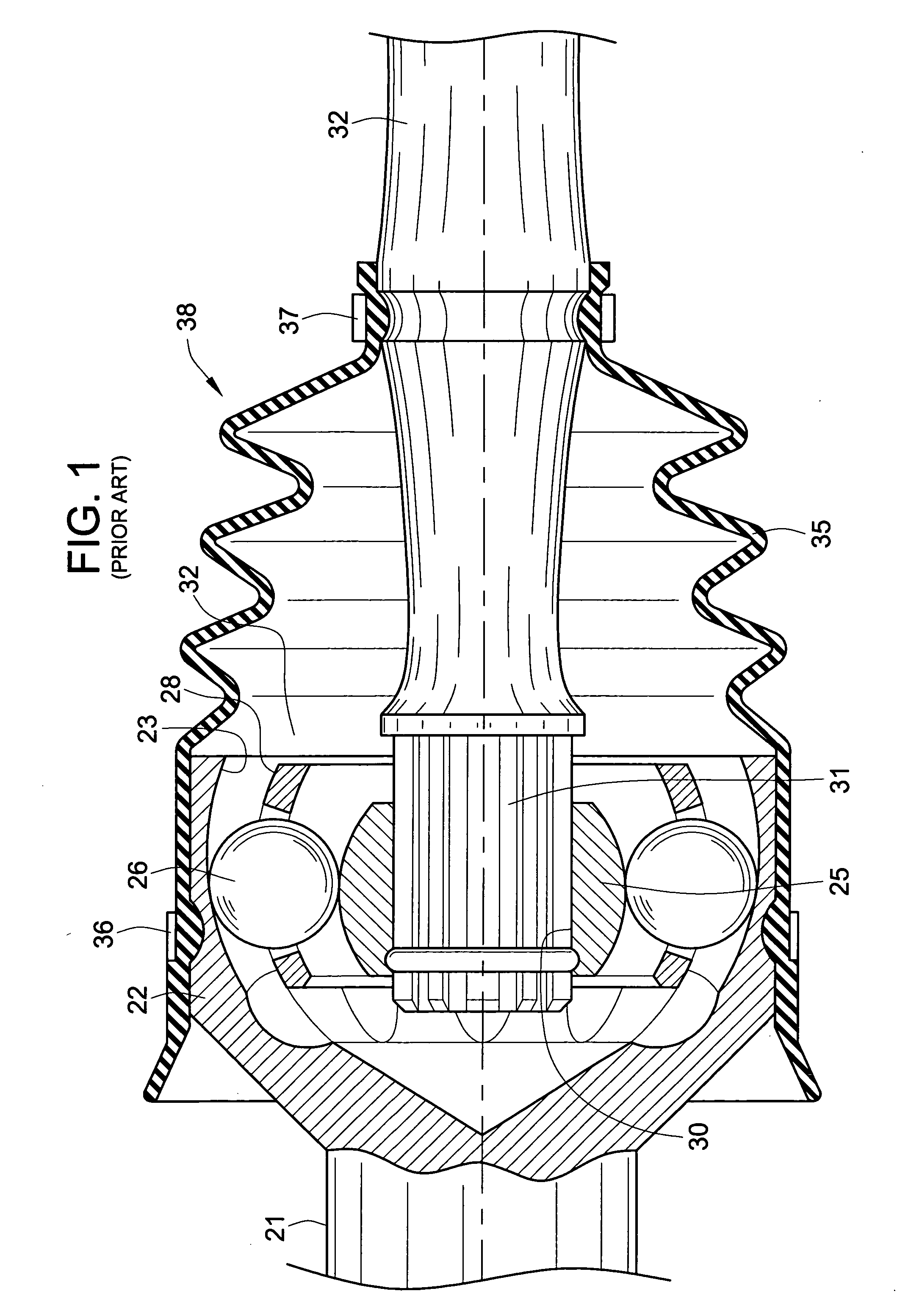
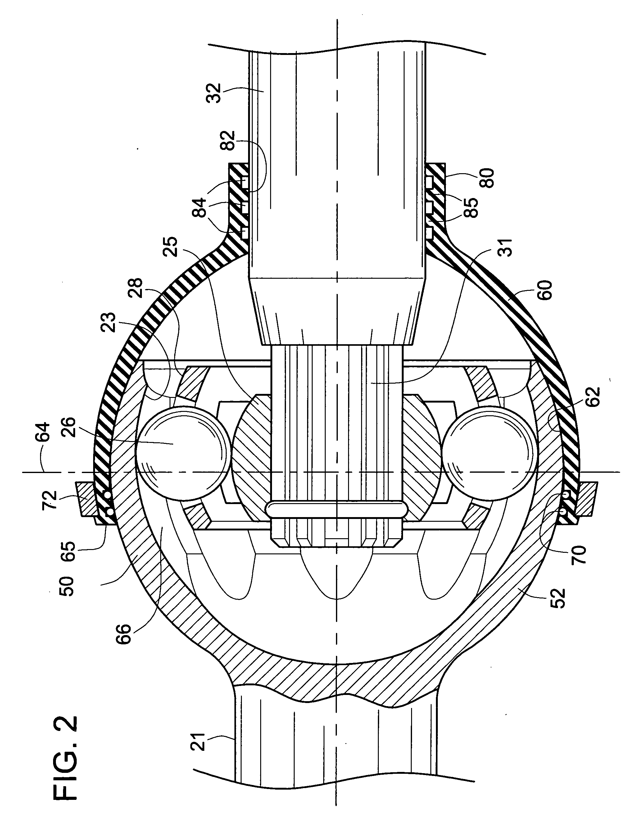
[0017] Turning now to the drawings, and particularly to FIG. 2, there is shown the components of a constant velocity joint used in practicing the present invention. Like FIG. 1, an input shaft 21 is coupled to an output shaft 32 by means of the constant velocity joint.

[0018] In the FIG. 2 embodiment an outer housing or body 50 of particular configuration encloses the remaining conventional elements of the constant velocity joint. The body has races 23, and the joint also includes an inner race 25, also having races, drive balls 26 and a cage 28. The inner race 25 has a splined opening to receive the splined end 31 of the output shaft 32. Thus, the shaft 32 can flex at any angle with respect to the input shaft 21. The maximum angle which can be accommodated without interference is on the order of 40 degrees.

[0019] The outer surface 52 of the body 50 is formed as a smooth spherical surface for purposes now to be described. In practicing the invention a semi-rigid plastic boot 60 is ...


PUM


Abstract

A high performance constant velocity universal joint is based on a body which encloses the constant velocity joint components and provides a smooth spherical outer surface. A one-piece semi-rigid plastic boot in the form of a truncated sphere has a smooth internal spherical surface sized to match the outer surface of the body. The plastic of the boot is sufficiently elastic to allow the boot to snap over the body, yet sufficiently resilient to snap the open end closed after the boot is snapped over the body to provide a substantial seal preventing entry of debris under the seal. A retaining ring is positioned on the boot near the truncated end to resist plastic creep which would result in enlarging the opening and allowing debris to enter the seal.

Description

FIELD OF THE INVENTION [0001] This invention relates to constant velocity joints, and more particularly to those capable of being used in adverse environmental conditions. BACKGROUND OF THE INVENTION [0002] Constant velocity joints are used in numerous vehicular applications where the rotational velocity oscillation of a conventional cardan joint is unacceptable. For example, in the front suspension of a front wheel drive automobile, there will be two constant velocity joints per axle. They are also used in off-road heavy-duty equipment, in trucks, and in high performance recreation vehicles. [0003] When the application is not overly environmentally adverse, constant velocity joints are excellent. However, in environmentally unfriendly applications they are less desirable because of the problems of keeping dirt and debris out of the joint. A better understanding of that will be appreciated upon review of FIG. 1 which shows a conventional prior art constant velocity joint. [0004]FIG....

Claims


Application Information

Patent Timeline
Patent Type & Authority Applications(United States)
IPC IPC(8): F16C1/26
CPCF16D3/843Y10S464/906F16D3/845
Inventor CARLINI, SEAN M.FRANA, JOHN C.
Owner AIRCRAFT GEAR CORP
Why Eureka
Try Eureka