Methods and devices for improving cardiac output

a technology of cardiac output and cardiac valve, applied in the field of improving cardiac output, can solve the problems of reducing the ability of the heart to output oxygenated blood from the left side of the heart, reducing the output, and reducing the cardiac output of the hear

a technology of cardiac output and cardiac valve, applied in the field of improving cardiac output, can solve the problems of reducing the ability of the heart to output oxygenated blood from the left side of the heart, reducing the output, and reducing the cardiac output of the hear

US20060241544A1Inactive Publication Date: 2006-10-26CORLIFE GBR

Image

  • Methods and devices for improving cardiac output
  • Methods and devices for improving cardiac output
  • Methods and devices for improving cardiac output

Examples


Embodiment Construction

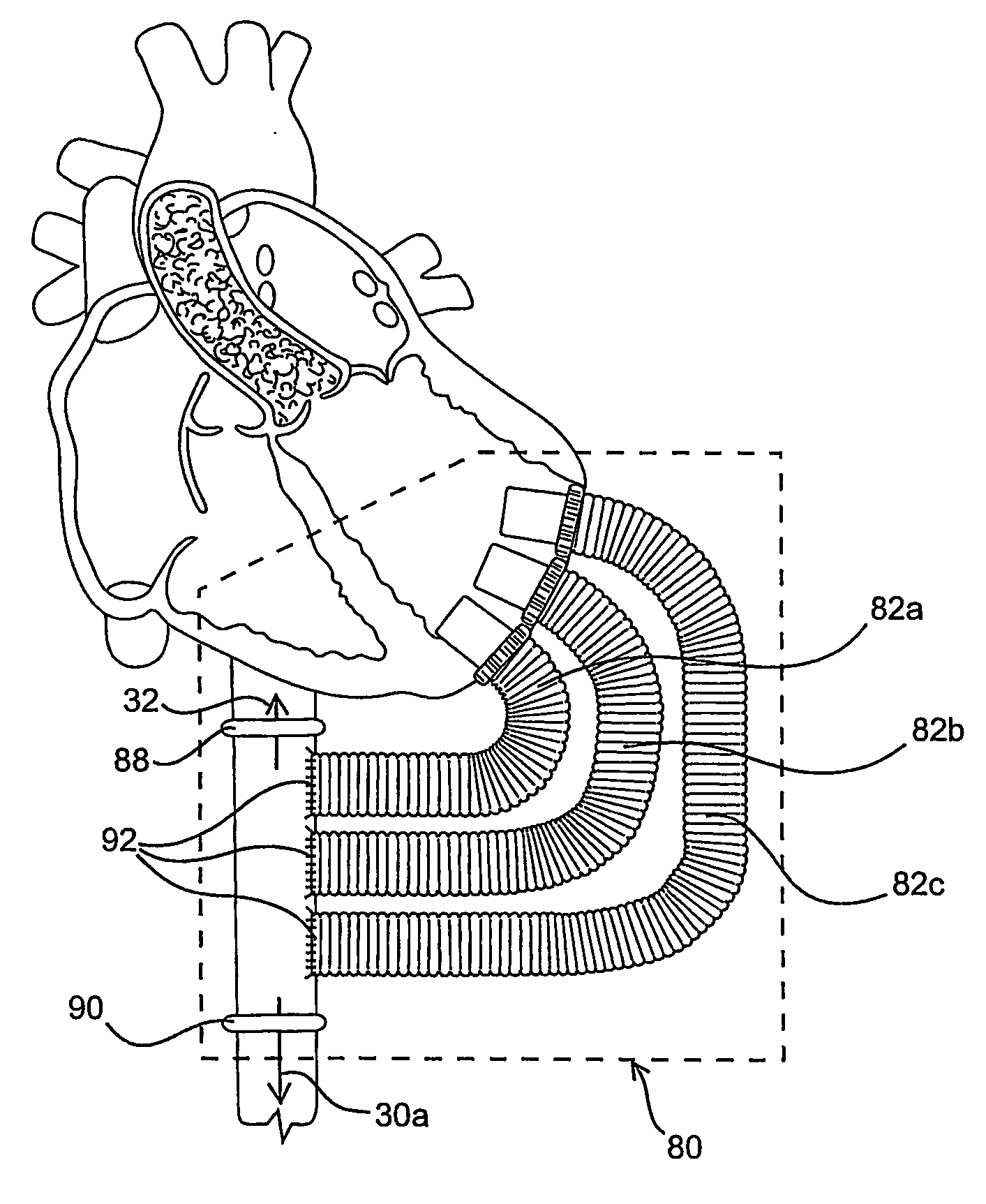
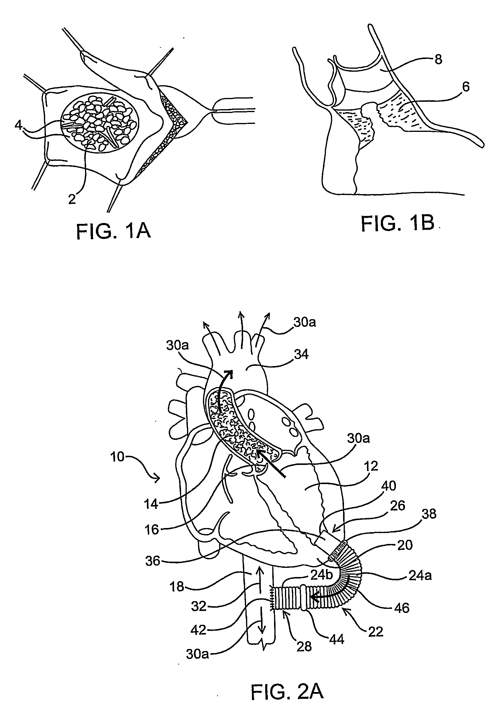
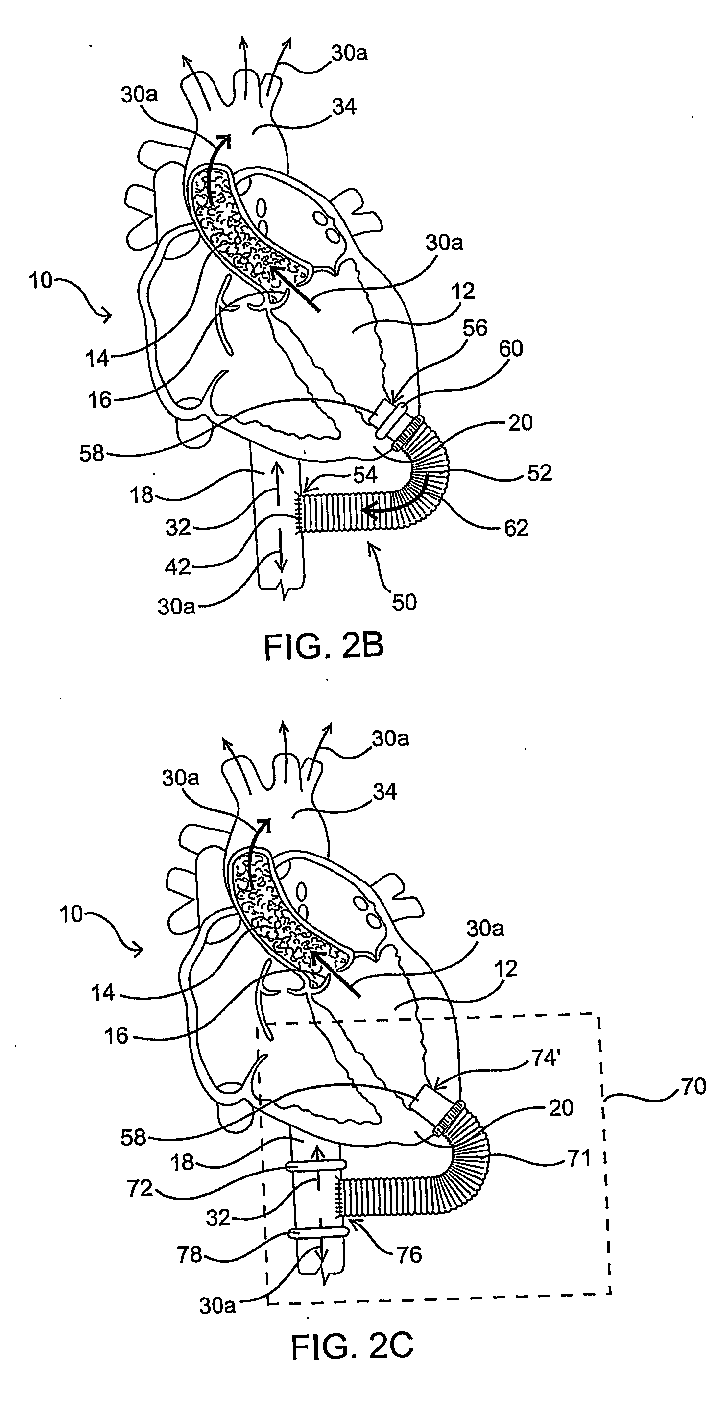
[0024] As mentioned above, the present invention includes devices, systems, methods and kits for establishing one or more blood flow conduits from the left ventricle of the heart to the aorta to compensate for a dysfunctional left ventricle.

[0025] Before the present invention is described in detail, it is to be understood that this invention is not limited to particular embodiments and applications described, as such may vary within the scope of the scope of the appended claims. For example, the following description of the invention is primarily described in the context of establishing a fluid communication connection between the left ventricle of the heart and the descending aorta; however, such description, with certain obvious modifications to the invention, is also intended to apply to such connections between the left ventricle and another natural or native structure, e.g., the ascending aorta; between another chamber of the heart to another native blood conduit, e.g., from t...


PUM


Abstract

Methods and devices are provided for improving cardiac output. The methods involve establishing a fluid communication pathway between the left ventricle and another natural or prosthetic structure. In one method, a conduit is implanted between the left ventricle and the descending aorta where ventricular blood flows from the left ventricle directly into the descending aorta and bypassing the aortic valve. The devices include such conduits and valves for forming the fluid communication pathways.

Description

FIELD OF THE INVENTION [0001] The present invention is directed to improving cardiac output. More particularly, the invention relates to devices and methods for establishing a blood flow conduit from the left ventricle of the heart to the aorta to improve cardiac output. BACKGROUND OF THE INVENTION [0002] A reduction in a heart's cardiac output, i. e., the reduced ability of the heart to output oxygenated blood from the left side of the heart, may result from various abnormalities and diseases of the heart. This reduction in output is typically due to aortic valve disease. There are two major categories of aortic heart valve disease: stenosis and regurgitation. Stenosis involves the narrowing of the aortic outflow tract, causing obstruction to blood flowing from the left ventricle into the ascending aorta. As illustrated in FIG. 1A, the stenosis typically involves the buildup of calcified material 2 on the valve leaflets 4, causing them to thicken and impairing their ability to full...

Claims


Application Information

Patent Timeline
26 Oct 2006
Publication
US20060241544A1
IPC
A61F2/06; A61B17/00; A61B17/11; A61B17/32; A61F2/24
CPC
A61B17/11; A61B17/32053; A61B2017/00252; A61F2/06; A61M1/1008; A61F2/24; A61F2/2412; A61F2/2475
Inventors
HAVERICH, AXEL