Energy based devices and methods for treatment of patent foramen ovale

a technology of energy-based devices and treatments, applied in the field of medical devices and methods, can solve the problems of still having one or more small gaps or openings

Inactive Publication Date: 2006-10-26
TERUMO KK
View PDF99 Cites 49 Cited by
  • Summary
  • Abstract
  • Description
  • Claims
  • Application Information

AI Technical Summary

Benefits of technology

[0017] In some embodiments of the present invention, devices and methods further provide for bringing tissues adjacent a PFO together (or “apposing” tissues). In various embodiments, tissues may be apposed before, during and / or after application or removal of energy to the tissues. Generally, energy application or removal will act to denature collagen in the PFO tissues. If the tissues are apposed before and / or during denaturation and / or while the collagen in the tissues is allowed to renature, the collagen in once-separated tissues binds together to bring the tissues together. Therefore, although not required, some embodiments of the invention include one or more devices for bringing (and possibly holding) tissues together before, during and / or after energy application or removal. Such devices include, for example, PFO tissue covering members, which may also be suction or vacuum application members, expandable members within the PFO tunnel, distal tip members for contacting a left atrial surface of PFO tissue and the like. By providing for substantial, acute closure of a PFO, devices and methods of the invention may be advantageous for preventing stroke, treating migraine headaches and / or preventing or treating other medical conditions caused or exacerbated by PFO.
[0021] In some embodiments, the method further includes retracting a sheath portion of the guide catheter to expose an expanding member within the PFO, the exposed expanding member bringing the tissues adjacent the PFO at least partially together. Such an expanding member may provide lateral force to the tissues adjacent the PFO, for example, and in some embodiments will do so without extending into the left atrium. As is explained further below, such expanding members may comprise “fishmouth,” two-pronged members in one embodiment, and may be constructed of shape memory materials, spring-loaded materials or the like. By spreading PFO tissues laterally between two prongs (for example), the tissues come together in the area between the prongs. Optionally, the method may also include contacting a left atrial surface of at least one of a septum primum and a septum secundum with a distal portion of the expanding member and retracting the expanding member to bring the tissues adjacent the PFO together. For example, the distal portion may contact the septum primum and pull it toward the right side of the heart, into contact with the septum secundum. At some point after the expanding member has been used to appose the tissues adjacent the PFO, it may be advantageous to retract the expanding member to a position within the guide catheter. For example, the expanding member may be retracted in some embodiments before removing the guide catheter through the main catheter device.
[0028] In some embodiments, the tissue covering member fully covers the opening of the PFO to allow blood pressure in a left atrium of the heart to bring the tissues together. Additionally, the tissue covering member may comprise a suction member for applying vacuum force to the tissues to bring the tissues together. Optionally, the tissue covering member may be expandable from a first delivery dimension to a second treatment dimension. In some embodiments, the catheter fuirther comprises a flexible isolation portion disposed between the tissue covering member and the catheter device to prevent unwanted movement of the tissue covering member during use. In some embodiments, the at least one energy transmission member is coupled with the tissue covering member.

Problems solved by technology

A substantially closed PFO, however, may still have one or more small gaps or openings, which will in at least some cases close over time via the healing process.

Method used


Image

  • Energy based devices and methods for treatment of patent foramen ovale
  • Energy based devices and methods for treatment of patent foramen ovale
  • Energy based devices and methods for treatment of patent foramen ovale

Examples


Embodiment Construction

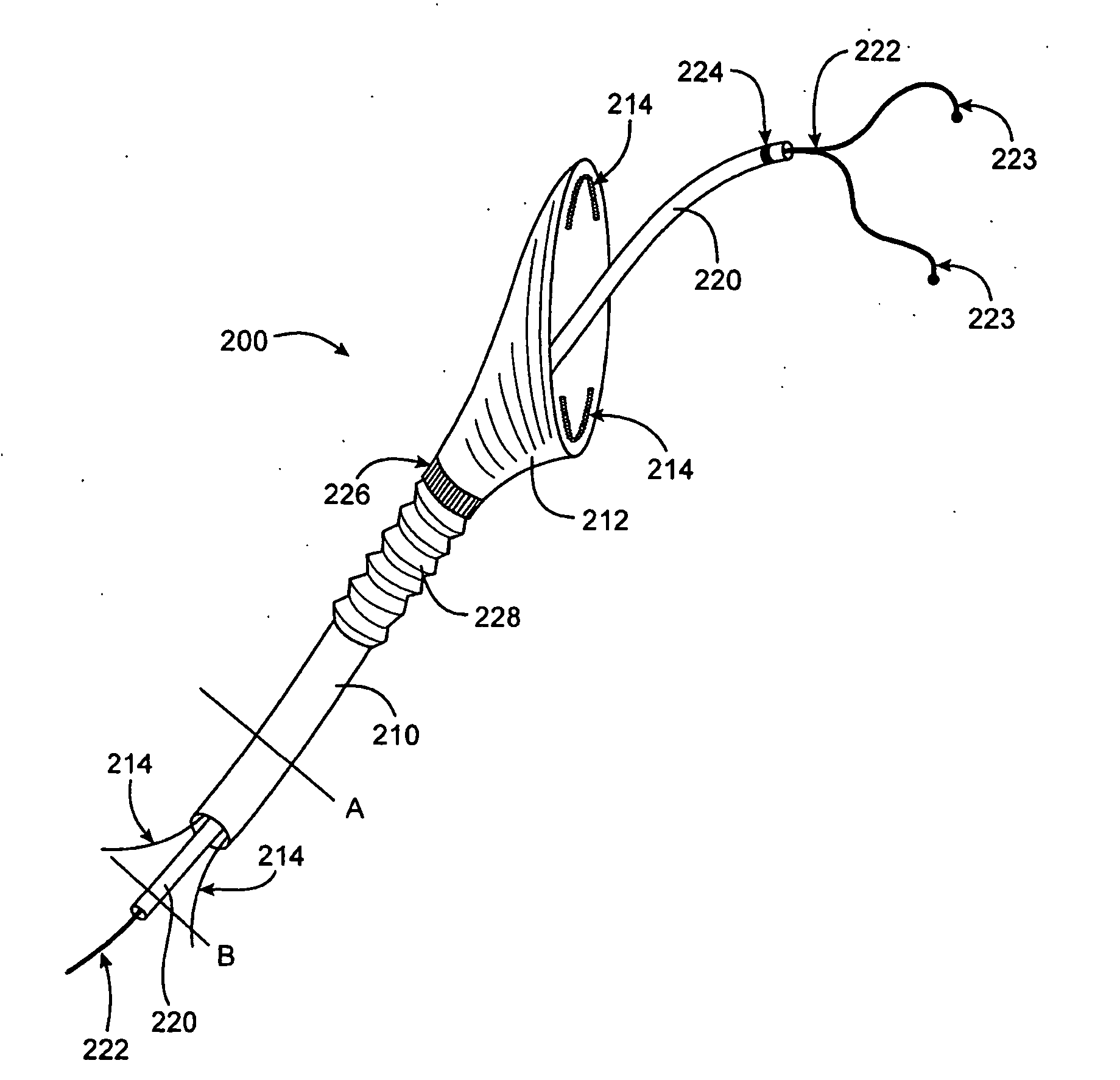
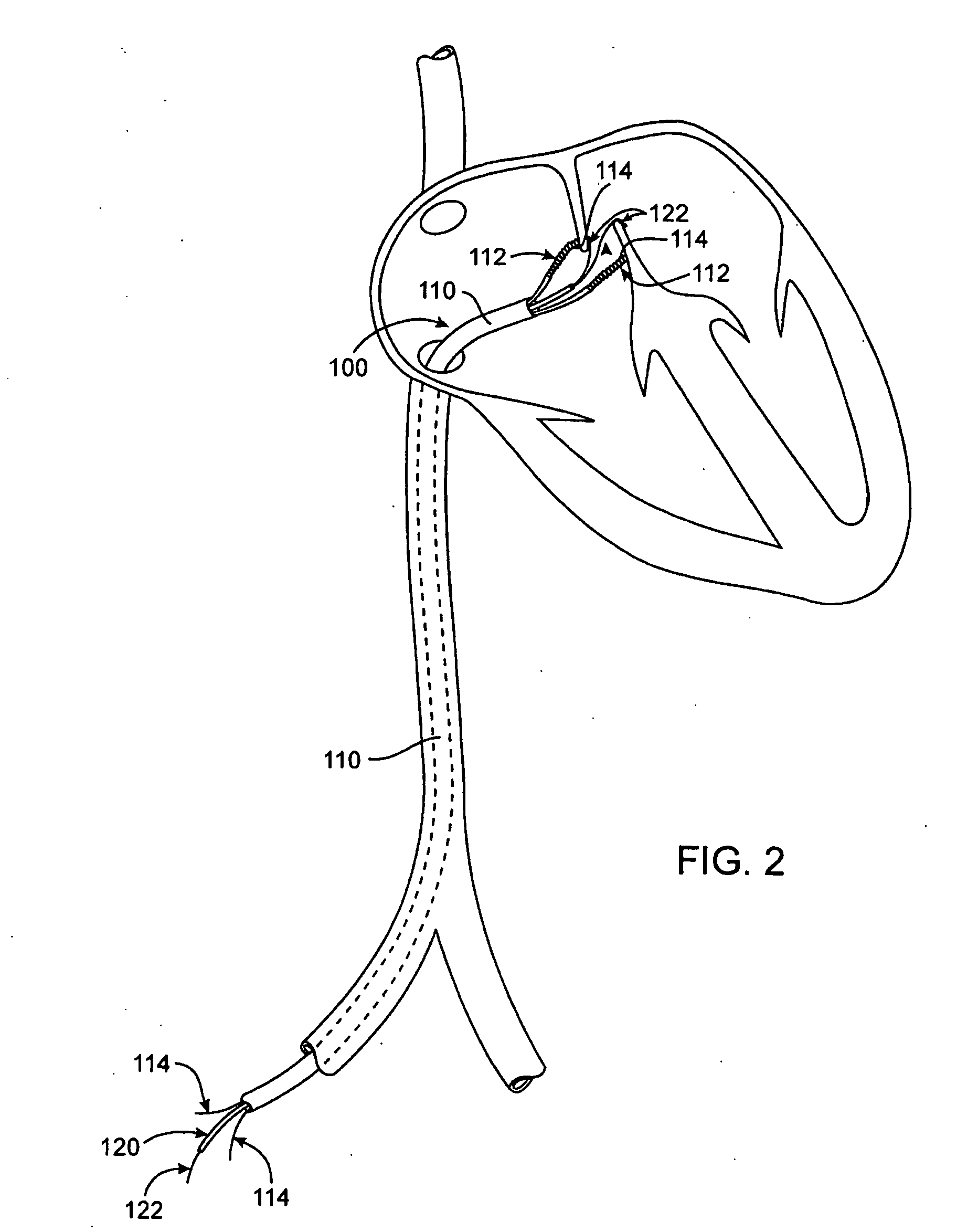
[0050] Devices and methods of the present invention generally provide for patent foramen ovale (PFO) treatment through application or removal of energy. Methods involve advancing a catheter device to a position in the heart for treating the PFO and applying energy to (or removing energy from) tissues adjacent a PFO to substantially close the PFO acutely. Terms such as “substantially,”“acutely,” and “tissues adjacent the PFO” are defined above in the Brief Summary of the Invention. Devices of the invention generally include a catheter device having a proximal end and a distal end and at least one energy transmission member adjacent the distal end for applying energy to or removing energy from tissues adjacent the PFO.

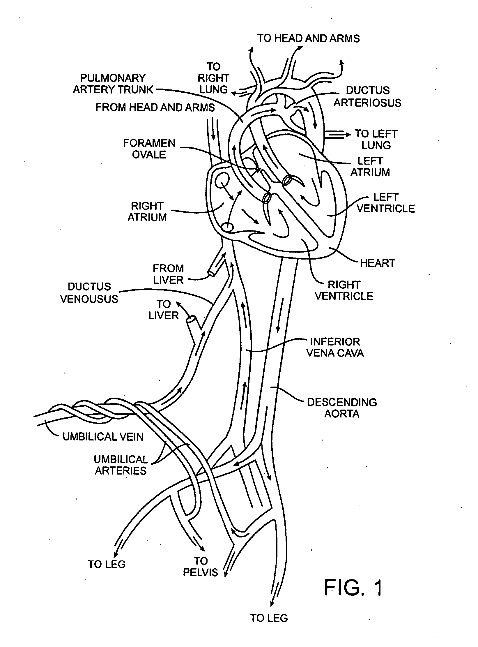
[0051] As mentioned above in the background section, FIG. 1 is a diagram of the fetal circulation. The foramen ovale is shown, with an arrow demonstrating that blood passes from the right atrium to the left atrium in the fetus. After birth, if the foramen ovale fails to...


PUM


Abstract

Methods and apparatus for treatment of patent foramen ovale (PFO) provide for applying energy to tissues adjacent the PFO with a catheter device to substantially close the PFO acutely. Apparatus generally includes a catheter device having at least one energy transmission member at or near its distal end configured to apply energy to PFO tissues to acutely, substantially close the PFO. Applied energy may be monopolar or bipolar radiofrequency energy or any other suitable energy, such as laser, microwave, ultrasound, resistive heating or the like. Some embodiments of a catheter device fuirther include one or more tissue apposition members near the distal end for helping bring PFO tissues together, such as a PFO covering member, a vacuum applying member and / or the like. PFO closure via energy-based approaches of the invention may help prevent stroke, treat migraine headache, and possibly treat or prevent other medical conditions.

Description

CROSS-REFERENCES TO RELATED APPLICATIONS [0001] This application is a continuation of U.S. patent application Ser. No. 11 / 249,566 (Attorney Docket No. 022128-000202US), filed Oct. 12, 2005, which is a continuation of U.S. patent application Ser. No. 10 / 958,533 (Attorney Docket No. 022128-000201US), filed Oct. 4, 2004, which was a divisional of U.S. patent application Ser. No. 10 / 679,245 (Attorney Docket No. 022128-000200US), filed Oct. 4, 2003, which claimed priority to U.S. Provisional Patent Application Nos.: 60 / 458,854 (Attorney Docket No. 022128-000100US (formerly 020979-002100US)), filed Mar. 27, 2003; 60 / 478,035 (Attorney Docket No. 022128-000110US (formerly 020979-002110US)), filed Jun. 11, 2003; and 60 / 490,082 (Attorney Docket No. 022128-000120US (formerly 020979-002120US)), filed Jul. 24, 2003, the full disclosures of which are incorporated herein by reference. This application is related to U.S. patent application Ser. No. 10 / 665,974 (Attorney Docket No. 022128-000300US (f...

Claims


Application Information

Patent Timeline
Patent Type & Authority Applications(United States)
IPC IPC(8): A61B18/14A61B19/00A61M25/10
CPCA61B17/0057C08L2201/12A61B17/0644A61B17/083A61B17/10A61B18/1477A61B18/1492A61B18/18A61B18/20A61B2017/00243A61B2017/00575A61B2017/00579A61B2017/00592A61B2017/00597A61B2017/0061A61B2017/00615A61B2017/00623A61B2017/00668A61B2017/00867A61B2017/0641A61B2017/0645A61B2017/0649A61B2018/00011A61B2018/00214A61B2018/00261A61B2018/00285A61B2018/00291A61B2018/00351A61B2018/00619A61B2018/0063A61B2018/00702A61B2018/00791A61B2018/00875A61B2018/1425A61B2018/1472A61B2019/5217A61N7/022A61B17/0218A61B2090/3614
Inventor MALECKI, WILLIAMFRANCIS, DANHORNE, KENNETHDEEM, MARK E.GIFFORD, HANSON S. IIIALEJANDRO, JOSE
Owner TERUMO KK
Why Eureka
Try Eureka