Integrated ultrasonic inspection probes, systems, and methods for inspection of composite assemblies

a composite assembly and ultrasonic technology, applied in the direction of instruments, heat measurement, specific gravity measurement, etc., can solve the problems of semi-automated inspection systems that require access to both sides, features and characteristics of many structures that cannot easily permit non-destructive inspection, etc., to achieve fast and efficient methods and facilitate inspection of structures

Inactive Publication Date: 2006-11-02
THE BOEING CO
View PDF90 Cites 97 Cited by
  • Summary
  • Abstract
  • Description
  • Claims
  • Application Information

AI Technical Summary

Benefits of technology

[0013] Improved apparatus, systems, and methods are provided for inspecting structures such as fuselage frames with curved linear U-shaped cross-section structural features and fuselage shear ties with L-shaped individual flange structural features using one or more inspection sensors with a portable function support system. Embodiments of apparatus and systems of the present invention use parts, such as a sensor holder, which may typically be constructed from rapid prototyping, wherein the sensor holder is configured to support an ultrasonic inspection sensor aligned for inspection of at least a portion of a surface of a structure. Embodiments of methods of the present invention provide fast and efficient methods for inspecting structures with inspection probes designed to accommodate unusually shaped structures and a portable function support systems to facilitate inspection of the structures by the probes.

Problems solved by technology

For example, typical defects in composite sandwich structures, generally made of one or more layers of lightweight honeycomb or foam core material with composite or metal skins bonded to each side of the core, include disbonds which occur at the interfaces between the core and the skin or between the core and a buried septum or delamination which may occur between adjacent composite layers.
However, the features and characteristics of many structures do not easily permit non-destructive inspection.
Non-destructive ultrasonic testing often involves coupling an ultrasonic signal from a transducer or transducer array to the surface of the structure under inspection, such as bubbling water between an inspection device and the structure.
However, for through-transmission ultrasonic inspection, a semi-automated inspection system requires access to both sides of a structure which, at least in some circumstances, will be problematic, if not impossible, particularly for semi-automated systems that use a fixed frame for control of automated scan heads.
Conventional automated scanning systems, such as the AUSS-X system, therefore require access to both sides of a structure for through transmission inspection which, at least in some circumstances, will be problematic, if not impossible, particularly for very large or small structures.
Constructing specialized inspection devices for each inspection application conventionally has required significant time and financial and human resources to design and build these specialized inspection devices.
Also, conventionally, each specialized inspection device is designed for and capable of only inspecting one structure, and typically cannot adjust for different sizes of the structure or different inspection applications that use different sensors.

Method used


Image

  • Integrated ultrasonic inspection probes, systems, and methods for inspection of composite assemblies
  • Integrated ultrasonic inspection probes, systems, and methods for inspection of composite assemblies
  • Integrated ultrasonic inspection probes, systems, and methods for inspection of composite assemblies

Examples


first embodiment

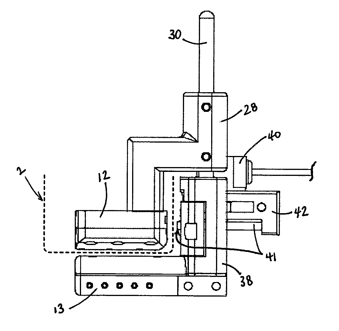
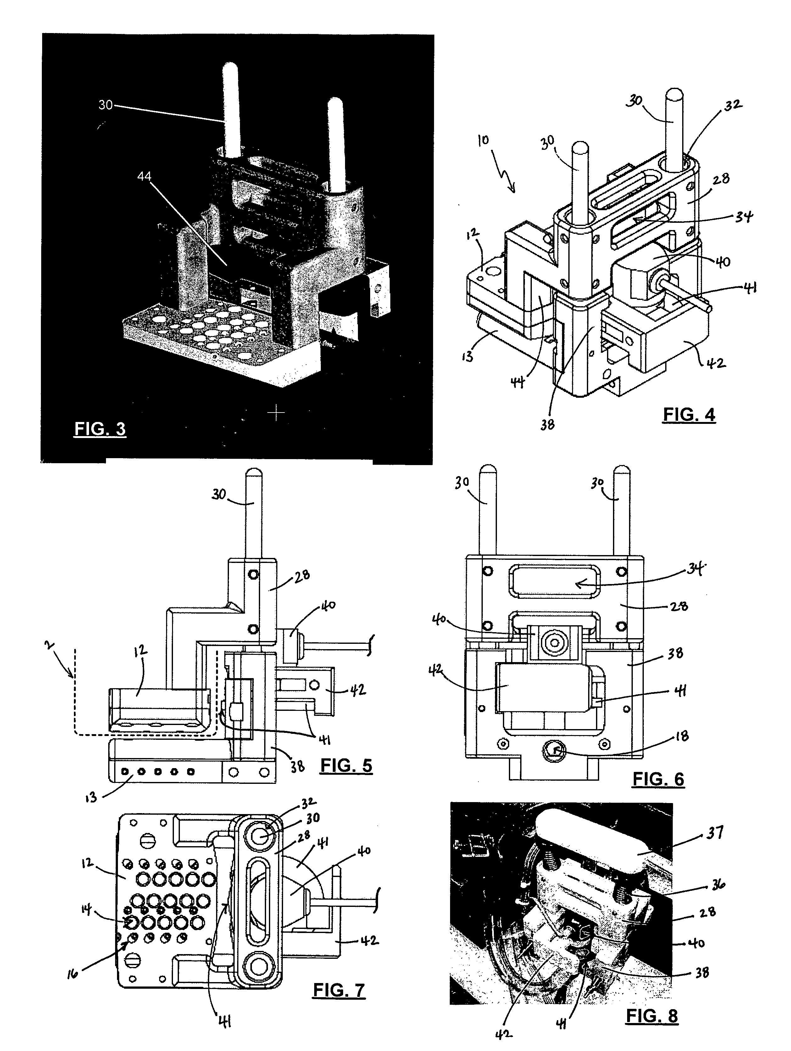
[0068]FIGS. 3-8 show a probe of the present invention designed for TTU inspection of the web portion of a fuselage frame. Accordingly, FIG. 3 is a perspective view of a fuselage frame inspection device of an embodiment of the present invention for inspecting flanges of fuselage frames; FIG. 4 is another perspective view of the inspection device of FIG. 3; FIG. 5 is a side plan view of the inspection device of FIG. 3; FIG. 6 is a front plan view of the inspection device of FIG. 3; FIG. 7 is a bottom plan view of the inspection device of FIG. 3; and FIG. 8 is yet another a perspective view of inspection device of FIG. 3 shown in operation with a spring-loaded force mechanism, data wiring connected to ultrasonic transducers and a positional rotary encoder, and fluid flow tubing. The cumulative collection of figures showing this inspection probe are discussed herein together below and specific reference to a particular figure is merely a convenient reference for visual identification in...

second embodiment

[0078]FIGS. 9-14 show a probe of the present invention designed for TTU inspection of the flange portion of a fuselage frame. Accordingly, FIG. 9 is a perspective view of a fuselage frame inspection device of an embodiment of the present invention for inspecting webs of fuselage frames; FIG. 10 is another perspective view of the inspection device of FIG. 9; FIG. 11 is yet another perspective view of the inspection device of FIG. 9 shown in operation with a spring-loaded force mechanism, data wiring connected to ultrasonic transducers and a positional rotary encoder, and fluid flow tubing; FIG. 12 is a top plan view of the inspection device of FIG. 9; FIG. 13 is a side plan view of the inspection device of FIG. 9; and FIG. 14 is a front plan view of the inspection device of FIG. 9. The cumulative collection of figures showing this inspection probe are discussed herein together below and specific reference to a particular figure is merely a convenient reference for visual identificati...

third embodiment

[0080]FIGS. 15-19 show a probe of the present invention designed for TTU inspection of the radius portion of a fuselage frame. Accordingly, FIG. 15 is a perspective view of a fuselage frame inspection device of an embodiment of the present invention for inspecting radii between webs and flanges of fuselage frames; FIG. 16 is another perspective view of the inspection device of FIG. 15; FIG. 17 is a top plan view of the inspection device of FIG. 15; FIG. 18 is a side plan view of the inspection device of FIG. 15; and FIG. 19 is a front plan view of the inspection device of FIG. 15. The cumulative collection of figures showing this inspection probe are discussed herein together below and specific reference to a particular figure is merely a convenient reference for visual identification in such figure and not a distinction from any other figure for the inspection probe except were specifically noted.

[0081] While the inspection probe of FIG. 15 is still designed to perform TTU inspecti...


PUM

PropertyMeasurementUnit
diametersaaaaaaaaaa
frequencyaaaaaaaaaa
voltageaaaaaaaaaa

Abstract

Apparatus, systems, and methods for inspecting a structure are provided which permit inspection of uniquely shaped structures such as fuselage frames and shear ties. Probes may be constructed from rapid prototyping. Inspection may be performed manually and may use a portable function support system for delivering fluid couplant, controlling transmit and receive functions of the inspection sensors, and delivering immediate visual analysis for an operator. Integrated ultrasonic inspection apparatus, systems, and methods facilitate fast and efficient custom inspection devices and inspecting otherwise difficult-to-inspect structures.

Description

CROSS-REFERENCE TO RELATED APPLICATIONS [0001] This application is a continuation-in-part of co-pending application Ser. No. 11 / 368,557, entitled “Integrated Curved Linear Ultrasonic Transducer Inspection Apparatus, Systems, and Methods,” filed Mar. 6, 2006, which is a continuation-in-part of co-pending application Ser. No. 11 / 213,652, entitled “Rapid Prototype Integrated Curved Linear Ultrasonic Transducer Inspection Apparatus, Systems, and Methods,” filed Aug. 26, 2005; application Ser. No. 10 / 949,625, entitled “Multi-Channel Multiplexed Inspection System and Method,” filed Sep. 24, 2004; application Ser. No. 11 / 178,584, entitled “Ultrasonic Inspection Apparatus, System, and Method,” filed Jul. 11, 2005; and application Ser. No. 11 / 178,637, entitled “Ultrasonic Array Probe Apparatus, System, and Method for Traveling Over Holes and Off Edges of a Structure,” filed Jul. 11, 2005, the contents each of which are incorporated herein by reference in their entireties. [0002] The contents...

Claims


Application Information

Patent Timeline
Patent Type & Authority Applications(United States)
IPC IPC(8): G01N29/04
CPCG01N29/043G01N29/0645G01N29/226G01N29/265G01N2291/2694G01N2291/0231G01N2291/0422G01N2291/106G01N29/28B33Y80/00G01N29/04
Inventor BUI, HIEN T.YOUNG, FRED D.LEE, MARK A.KROTZER, RICHARD C.UYEHARA, CLYDE T.FETZER, BARRY A.
Owner THE BOEING CO
Why Eureka
Try Eureka