
Cylindrical element cleaning assemblies and related methods

a technology of cylindrical elements and cleaning assemblies, applied in the field of cylindrical element cleaning assemblies, can solve the problems of reducing the enjoyment of users, reducing the convenience of users, and reducing the enjoyment of consumers, so as to improve the convenience of users and promote the effect of ease of us

Inactive Publication Date: 2006-11-02
PRESCOTT JAMES M +1
View PDF8 Cites 25 Cited by
  • Summary
  • Abstract
  • Description
  • Claims
  • Application Information

AI Technical Summary

Benefits of technology

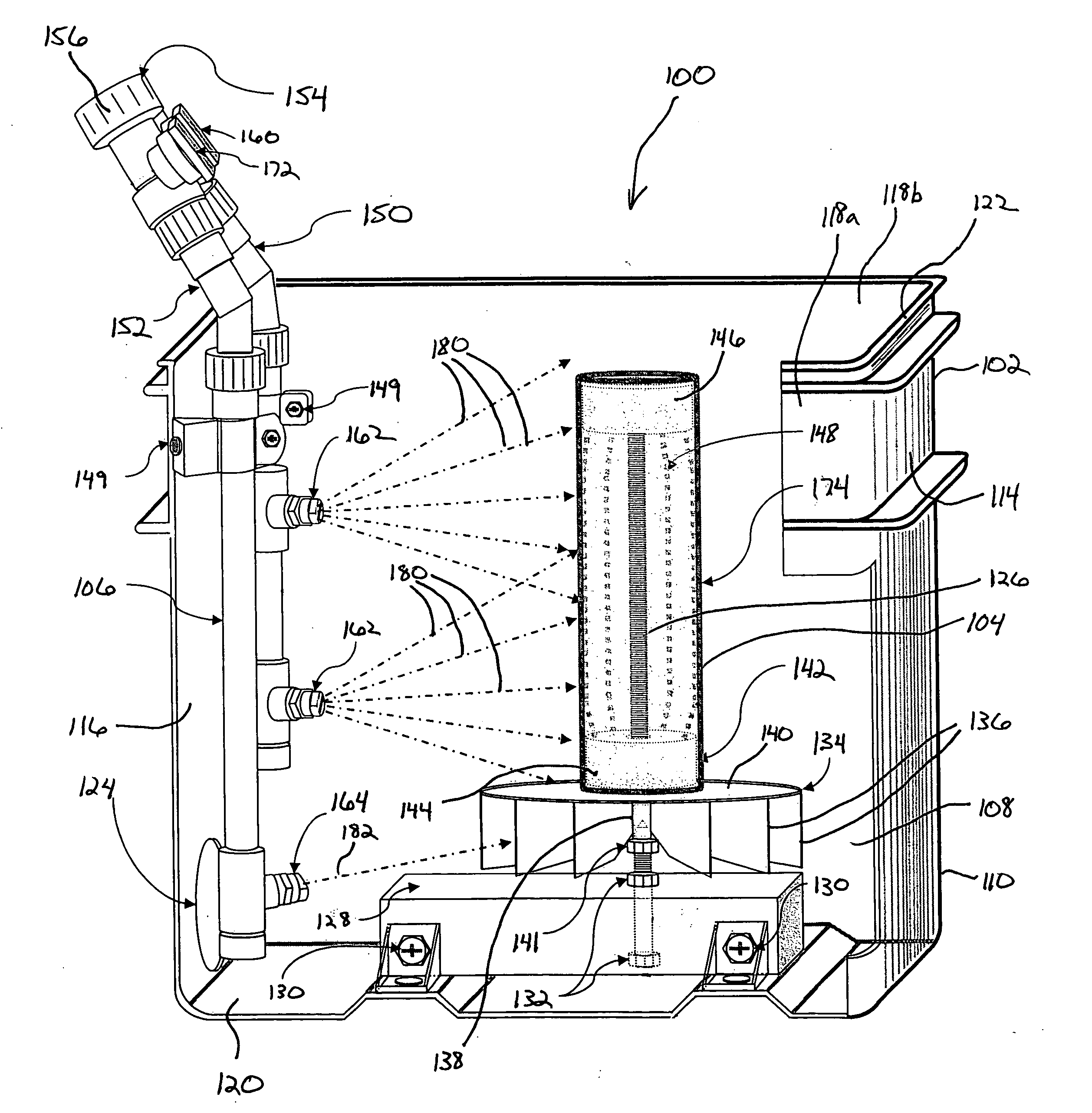
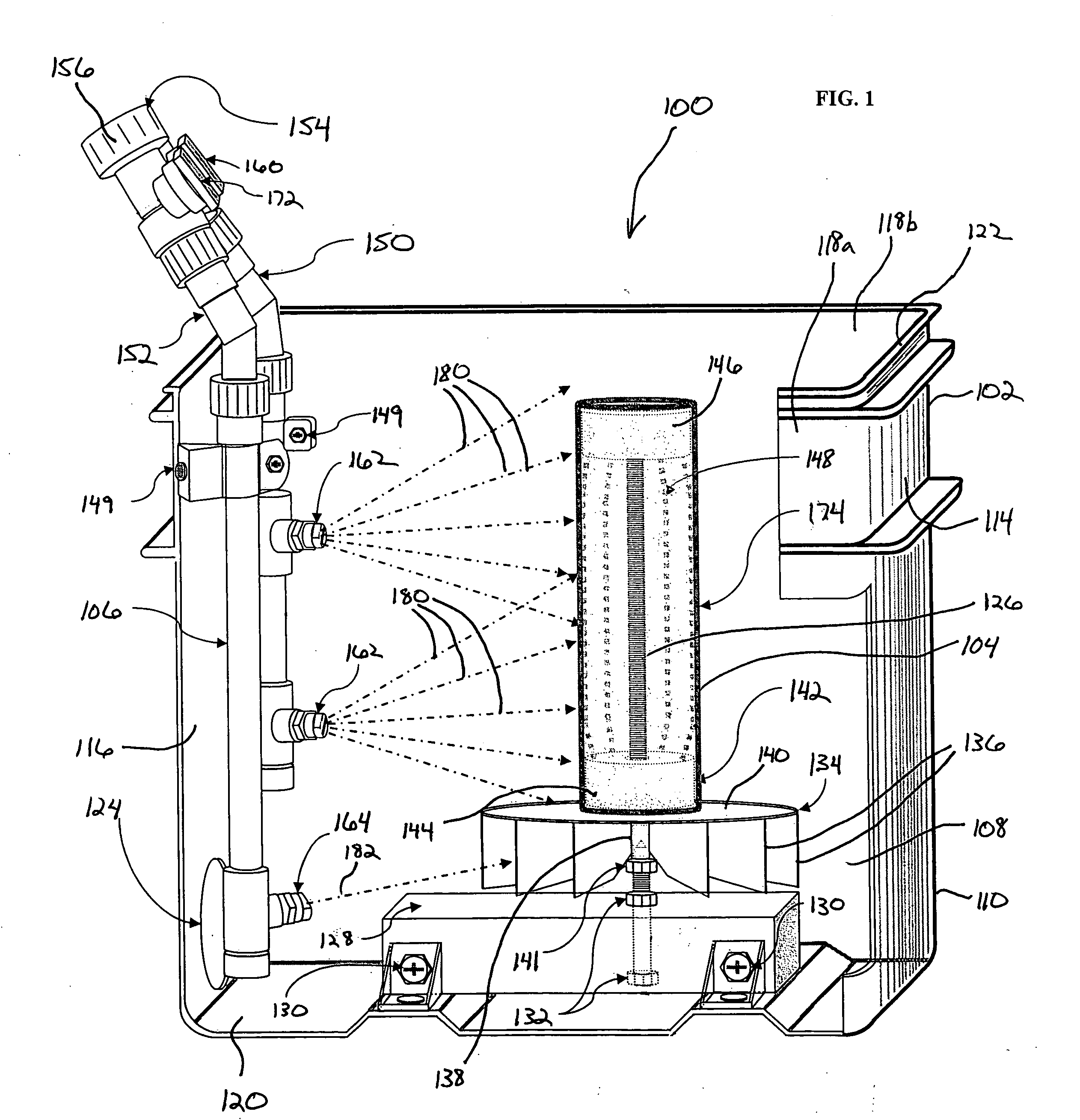
[0008] The present invention is directed to a cleaning assembly having improved convenience for a user cleaning cylindrical elements such as, for example, paint rollers, pool filters and spa filters. A cleaning assembly of the present invention improves convenience for the user through a design promoting ease of use, reduction of messiness and improved drying to restore effective use of the cylindrical element. A cleaning assembly of the invention can include a housing assembly, a cylindrical element mounting assembly and a water jet assembly that cooperatively eliminate the mess and hassle typically associated with cleaning cylindrical elements. The housing assembly can include a base portion and a hinged cover for providing physical and visible access to the inside of the base portion. The cylindrical element mounting assembly can comprise a roller cage configured to accept and vertically position cylindrical elements of varying sizes on a paddlewheel assembly. The water jet assembly can include a manifold structure permanently attached to a side wall of the base portion and including at least two water jets wherein at least one water jet is adjusted to spray the cylindrical element within the roller cage and wherein at least one water jet is adjusted to spray the paddlewheel assembly to impart rotational motion to the cylindrical element mounting assembly during cleaning and drying cycles.
[0009] In one aspect, a representative cleaning assembly of the present invention can comprise a housing assembly having a base portion and a cover portion for fully enclosing a cylindrical element during cleaning and drying cycles. The cover portion is preferably pivotally attached to the base portion to allow quick physical access for install and removing cylindrical elements. In addition, the cover portion allows visible access during either the cleaning or drying cycle so as to allow a user to visually confirm that the cylindrical element is being cleaned or dried.
[0010] In another aspect, a representative cleaning assembly of the present invention can comprise a cylindrical element mounting assembly for successfully accommodating a variety of cylindrical element sizes. The cylindrical element mounting assembly can comprise a roller filter cage over which the cylindrical element is installed for cleaning and drying. The roller filter cage can permanently or releasably engage a paddlewheel assembly that interfaces with a hydraulic energy source for spinning the cylindrical mounting assembly to accelerate the cleaning and drying process.
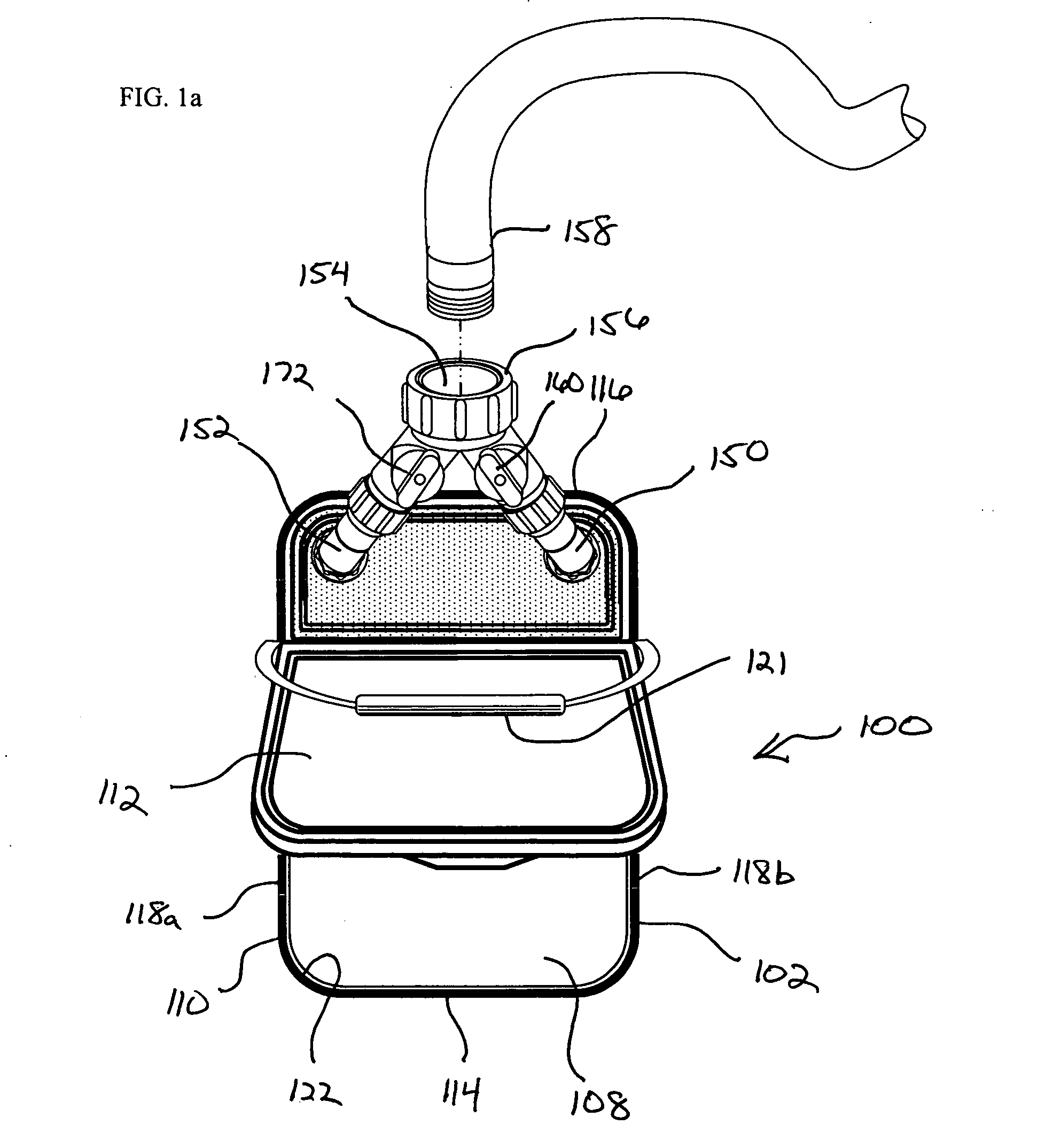
[0012] In another aspect, a representative cleaning assembly of the present invention can comprise a portable cleaning assembly wherein the entire cleaning assembly can be hand-carried to a point-of-use and directly connected to water sources such as, for example, a garden hose or utility sink. Through the use of a body portion having a pivotally attached cover, cylindrical elements can be quickly installed and removed before and after cleaning. As the cylindrical elements are fully enclosed during cleaning and drying cycles, the cleaning assembly can be used indoors or out without concern for splashing water and contaminants such as particulate matter and paint on the surroundings.
[0016] In another aspect, a representative cleaning assembly of the present invention can provide for cylindrical element cleaning and drying without direct supervision or intervention of a user once the cylindrical element has been operably positioned within an enclosure and a water source has been turned on.

Problems solved by technology

However, in other instances, these cylindrical elements have significant replacement cost.
Oftentimes, these water recirculation assemblies make use of filter cartridges for filtering particulate matter and other debris that may interfere with the proper operation of other circulation components or may reduce the enjoyment of the users.
This task of periodic rinsing and washing of the filter is considered by most consumers to be messy, difficult, time-consuming and generally less than desirable.
If the paint roller is to be reused following application of paint, the paint rollers must be quickly cleaned or rinsed before the paint hardens and the paint roller becomes unusable.
Even after cleaning, the nap can become hard when left to stand and dry such that the effectiveness of the paint roller is reduced.

Method used


Image

  • Cylindrical element cleaning assemblies and related methods
  • Cylindrical element cleaning assemblies and related methods
  • Cylindrical element cleaning assemblies and related methods

Examples


Embodiment Construction

[0030] An embodiment of a cleaning assembly 100 for cleaning and drying cylindrical elements is illustrated in FIGS. 1, 1a and 5. The cleaning assembly 100 generally comprises a housing assembly 102, an element mounting assembly 104 for mounting said cylindrical element for cleaning and a water jet assembly 106 for supplying liquid jet sprays within an interior portion 108 of the housing assembly 102.

[0031] With reference to FIGS. 1, 1a and 5, housing assembly 102 generally comprises a base portion 110 and a cover 112. Base portion 110 generally comprises a front wall 114, a rear wall 116, a pair of side walls 118a, 118b and a floor 120. Base portion 110 is preferably sized to fit within a typical residential utility sink and can have an interior volume between about 3 gallons to about 13 gallons. Housing assembly 102 can include a handle 121 allowing for easy carrying and placement of the cleaning assembly 100. Cover 112 attaches at a top opening 122 of the base portion 110 to ful...


PUM

PropertyMeasurementUnit
lengthaaaaaaaaaa
lengthaaaaaaaaaa
lengthaaaaaaaaaa

Abstract

A portable cleaning assembly for cleaning cylindrical elements such as paint roller covers and pool and spa cartridge filters. The portable cleaning includes a housing structure for fully enclosing the cylindrical element during cleaning so as to prevent overspray and subsequent clean-up of the surrounding area. The housing structure further includes a top accessible door for positioning the cylindrical element for cleaning as well as allowing visible access during a cleaning, rinsing and / or drying step without interfering with operation of the cleaning assembly. The portable cleaning assembly includes a manifold assembly including a plurality of water jet assemblies for spraying the cylindrical elements. In addition, the portable cleaning assembly includes a turbine assembly upon which the cylindrical element is mounted and spun, under the direction of the water jet assemblies, during the cleaning operation.

Description

PRIORITY CLAIM [0001] The present application claims priority to U.S. Provisional Patent Application No. 60 / 666,294 filed Mar. 29, 2005, and entitled “FILTER CLEANING ASSEMBLY,” which is herein incorporated by reference in its entirety.FIELD OF THE INVENTION [0002] The present invention relates generally to the field of cleaning assemblies. More specifically, the present invention relates to a portable cleaning assembly using a combination of rotational energy and water jet streams for cleaning cylindrical elements such as paint rollers and spa and pool filters within an enclosed assembly. BACKGROUND OF THE INVENTION [0003] Removable cylindrical elements are used commonly in everyday life. For example, cylindrical elements can be configured as filters to remove contaminants from fluid streams or as paint rollers for quickly and evenly applying paint to surfaces such as walls and ceilings. In some instances, these cylindrical elements are inexpensively replaced following use. However...

Claims


Application Information

Patent Timeline
Patent Type & Authority Applications(United States)
IPC IPC(8): B08B3/00B08B7/00
CPCB01D41/04B44D3/006B08B3/02B08B3/006
Inventor PRESCOTT, JAMES M.VAN STONE, DOUGLAS
Owner PRESCOTT JAMES M
Learn More