Apparatus for hands-free dispensing of a measured quantity of material

a technology for measuring quantities and apparatuses, applied in the direction of liquid handling, instruments, horology, etc., to achieve the effect of facilitating the initial positioning of the apparatus and improving operation

Inactive Publication Date: 2006-11-02
JOSEPH S KANFER
View PDF42 Cites 102 Cited by
  • Summary
  • Abstract
  • Description
  • Claims
  • Application Information

AI Technical Summary

Benefits of technology

[0010] It has been found, therefore, that an apparatus for hands-free dispensing of measured quantities of fluid material can be provided which improves operation of the known hands-free fluid dispensing devices. In particular, initial positioning of the apparatus is facilitated by use of the object sensor such that prior to permanent installation of the apparatus and loading of the fluid material, the sensor indicates that the device is properly positioned for use. In other words, the infrared sensor sends out a test signal and if the apparatus is temporarily positioned in an undesirable location, indicia will turn off to indicate to the installer that this position is not appropriate. Accordingly, the installer will move the device to another position for location testing. If the lights turn on at this time, then the installer knows that this is an appropriate position for the infrared sensor and that installation of the device is proper in the position selected. Upon completion of the installation of the device the apparatus is loaded with a container of fluid material connected to a dispensing mechanism which deposits a measured quantity of material when the presence of an object is detected and without the user having to actuate a push bar or lever.

Problems solved by technology

In other words, the infrared sensor sends out a test signal and if the apparatus is temporarily positioned in an undesirable location, indicia will turn off to indicate to the installer that this position is not appropriate.

Method used


Image

  • Apparatus for hands-free dispensing of a measured quantity of material
  • Apparatus for hands-free dispensing of a measured quantity of material
  • Apparatus for hands-free dispensing of a measured quantity of material

Examples


Embodiment Construction

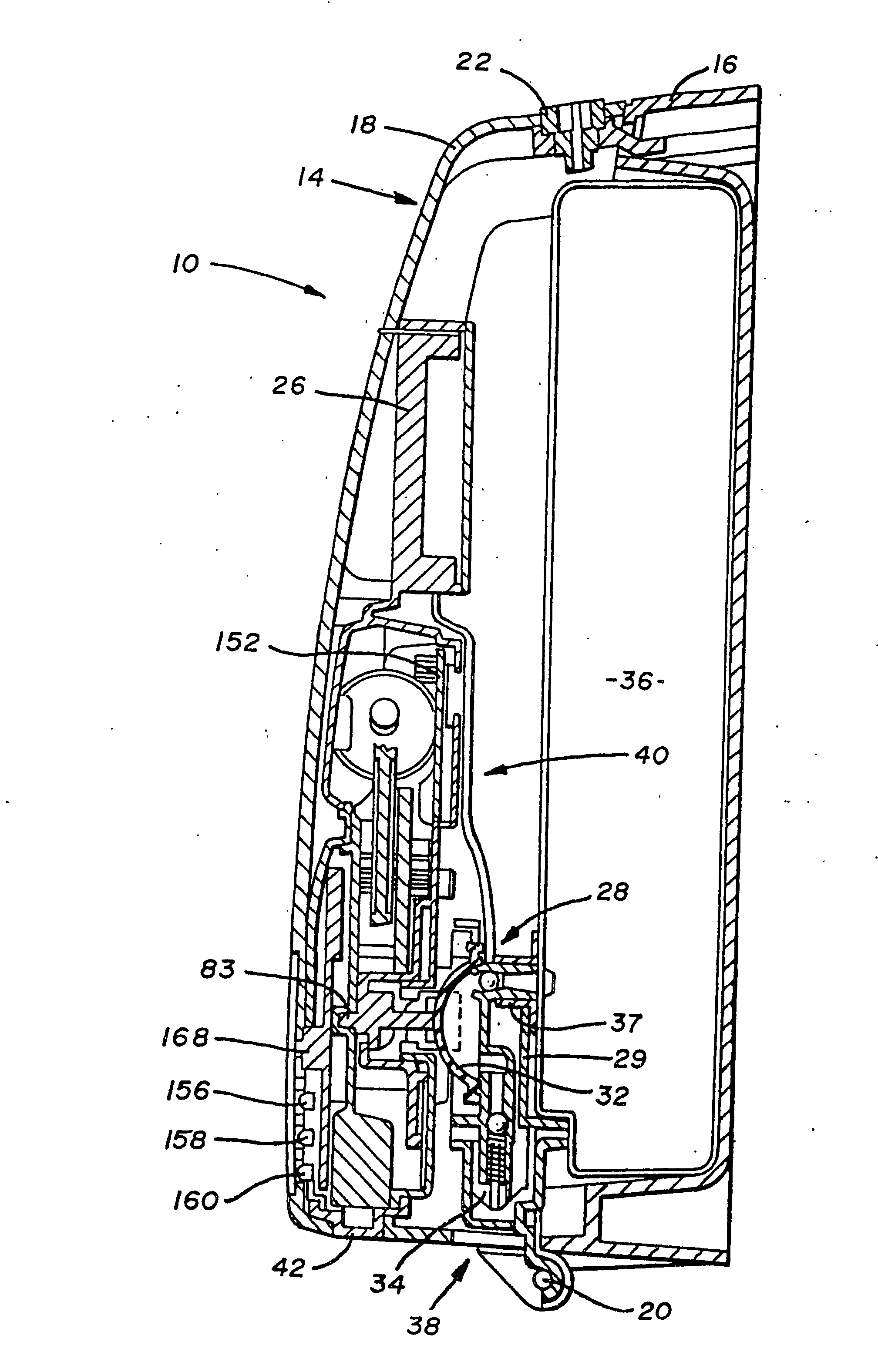
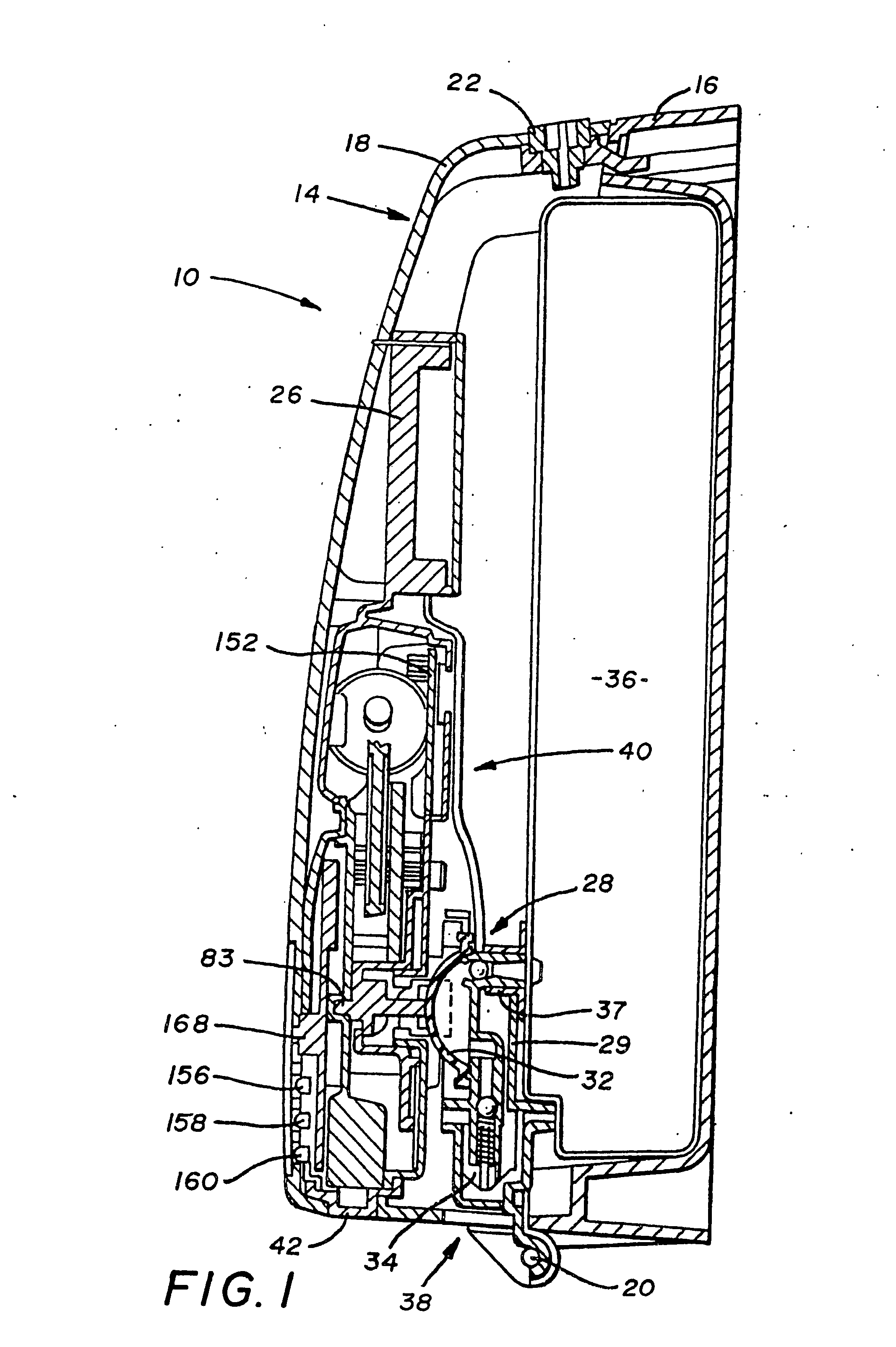
[0030]FIG. 1 depicts an apparatus or dispenser, generally designated by the numeral 10, for dispensing a measured quantity of material as a result of hands-free actuation. The dispenser 10, which may be a wall-mounted or a stand-alone device, includes a housing 14 having a back shell 16 mateable with a front shell 18. In the preferred embodiment, the back shell 16 and the front shell 18 are connected by a hinge 20 at an underside of the dispenser 10. If desired, the hinge mechanism may be placed on either side of the dispenser 10 or at its top. A key latch 22 is provided at the side opposite of the hinge 20 so as to hold the front shell 18 in a mated position with the back shell 16. This encloses the device and precludes its access by unauthorized personnel. Although a key latch is shown, it will be appreciated that other mechanisms for latching the two shells 16 and 18 to one another may be employed. The shells 16 and 18 are preferably manufactured of a rigid plastic material which...


PUM


Abstract

An apparatus for automatically dispensing a fluid includes a container adapted to carry a supply of fluid, and a valve connected to said container, wherein actuation of said valve dispenses the fluid. Also included is an apparatus position indicator proximally associated with the container and an object sensor positioned near the valve. The object sensor monitors an area below where the valve dispenses when open and upon detection of an object opens said valve. Initial positioning of the apparatus triggers the apparatus position indicator to generate an appropriate signal until said object sensor is properly positioned. Once positioned the device may be permanently secured. A control circuit within the apparatus also allows programming of lighting indicators, dispense cycle size, and dispense quantities. The control circuit also provides for overload protection, motor braking and RF shielding.

Description

RELATED PATENT APPLICATIONS [0001] This application claims the benefit of U.S. Provisional Application No. 60 / 456,794 filed on Mar. 21, 2003 and which is incorporated herein by reference.BACKGROUND OF THE INVENTION [0002] This invention relates, in general, to devices that discharge a measured quantity of cleaning material in response to a physical input. Moreover, this invention relates to improvements in the operation of the dispenser to facilitate ease of use. DESCRIPTION OF THE PRIOR ART [0003] Dispensers, either wall-mounted or stand-alone, are used to hold a quantity of cleaning material, soap, or other disinfecting material. The dispenser is typically positioned near a source of water which is used with the cleaning material to clean the user's hands. When a user needs a quantity of cleaning material, they actuate a lever or a pump so that a quantity of material is dispensed into their hand. Typically, a predetermined amount is dispensed. This can be adjusted by shortening th...

Claims


Application Information

Patent Timeline
Patent Type & Authority Applications(United States)
IPC IPC(8): B67D5/08B65D37/00B67D7/08A47K5/12B67D7/06
CPCA47K5/1217A47K5/1208
Inventor REYNOLDS, AARON R.VAN DEMAN, BRUCE J.O'TOOLE, MARTINWATERHOUSE, PAUL
Owner JOSEPH S KANFER
Why Eureka
Try Eureka