

Compositions comprising a fluoroolefin
- Summary
- Abstract
- Description
- Claims
- Application Information
AI Technical Summary
Benefits of technology
Problems solved by technology
Method used
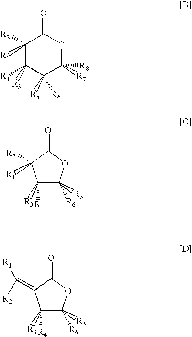
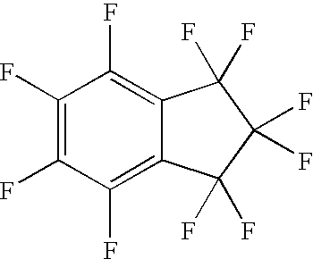
Image


Examples
example 1
Impact of Vapor Leakage
[0193] A vessel is charged with an initial composition at a temperature of either −25° C. or if specified, at 25° C., and the initial vapor pressure of the composition is measured. The composition is allowed to leak from the vessel, while the temperature is held constant, until 50 weight percent of the initial composition is removed, at which time the vapor pressure of the composition remaining in the vessel is measured. Results are shown in Table 9.
TABLE 9AfterAfter50%50%CompositionInitial PInitial PLeakLeakDelta Pwt %(Psia)(kPa)(Psia)(kPa)(%)HFC-1234yf / HFC-327.4 / 92.649.233949.23390.0%1 / 9949.233949.23390.0%20 / 8049.033848.83370.3%40 / 6047.532747.03241.0%57 / 4344.930940.52809.6%58 / 4244.630840.127610.2%HFC-1234yf / HFC-12510.9 / 89.140.828140.82810.0%1 / 9940.327840.22770.0%20 / 8040.527940.32780.4%40 / 6038.726737.02554.4%50 / 5037.425834.02359.0%51 / 4937.325733.72329.6%52 / 4837.125633.322910.3%HFC-1234yf / HFC-1341 / 9911.78111.6800.7%10 / 9012.88812.2844.5%20 / 8013.79513.0895.6%...
example 2
Refrigeration Performance Data
[0195] Table 10 shows the performance of various refrigerant compositions of the present invention as compared to HFC-134a. In Table 10, Evap Pres is evaporator pressure, Cond Pres is condenser pressure, Comp Disch T is compressor discharge temperature, COP is energy efficiency, and CAP is capacity. The data are based on the following conditions.
Evaporator temperature 40.0° F. (4.4° C.)Condenser temperature130.0° F. (54.4° C.)Subcool temperature 10.0° F. (5.5° C.)Return gas temperature 60.0° F. (15.6° C.)Compressor efficiency is100%
[0196] Note that the superheat is included in cooling capacity calculations.
TABLE 10EvapEvapCondCondCompCompCapCompositionPresPresPresPresDisch TDisch T(Btu / Cap(wt %)(Psia)(kPa)(Psia)(kPa)(F.)(C.)min)(kW)COPHFC-134a50.3346214147615668.92133.734.41HFC-1225ye / HFC-152a (85 / 15)39.8274173119315166.11733.034.45HFC-1225ye / HFC-3246.5321197135815166.12003.504.53(95 / 5)HFC-1225ye / HFC-3243.1297184126914965.01863.264.50(97 / 3)HFC-1225...
example 3
Refrigeration Performance Data
[0198] Table 11 shows the performance of various refrigerant compositions of the present invention as compared to R404A and R422A.
[0199] In Table 11, Evap Pres is evaporator pressure, Cond Pres is condenser pressure, Comp Disch T is compressor discharge temperature, EER is energy efficiency, and CAP is capacity. The data are based on the following conditions.
Evaporator temperature−17.8°C.Condenser temperature46.1°C.Subcool temperature5.5°C.Return gas temperature15.6°C.Compressor efficiency is70%
[0200] Note that the superheat is included in cooling capacity calculations.
TABLE 11EvapCond PComprPressPressDisch Twt %(kPa))(kPa)(C.)CAP (kJ / m3)EERExisting RefrigerantProductR22267177414416974.99R404A3302103101.117694.64R507A3422151100.318014.61R422A324212495.016994.54CandidateReplacementHFC-125 / HFC-85.1 / 11.5 / 3.4330213793.316994.501225ye / isobutaneHFC-125 / trans-HFC-86.1 / 11.5 / 2.4319209694.416694.521234ze / isobutaneHFC-125 / HFC-87.1 / 11.5 / 1.4343218693.317584.52...
PUM
| Property | Measurement | Unit |
|---|---|---|
| Temperature | aaaaa | aaaaa |
| Temperature | aaaaa | aaaaa |
| Percent by mass | aaaaa | aaaaa |
Abstract
Description
Claims
Application Information