Pin locking method and apparatus for pin-supported workpieces

a technology of pins and workpieces, applied in the direction of clamps, electrical equipment, manufacturing tools, etc., can solve the problems of printing circuit board flexure, unusability, and difficulty in supporting a double-sided board that has been partially populated on its underside, and achieve the effect of accurate pre-calculation, exceptional locking force, and inexpensive and robust pin locking mechanisms

Inactive Publication Date: 2006-11-02
ERDMANN GUNTER
View PDF26 Cites 20 Cited by
  • Summary
  • Abstract
  • Description
  • Claims
  • Application Information

AI Technical Summary

Benefits of technology

[0031] Moreover, with the subject support system, one can readily control the spacing of dispensing tips from a flat double-sided board for those operations requiring the dispensing of conductive epoxies or other adhesives at precise points with controlled lateral spreads. Since the subject locked pin array system maintains with vacuum warp correction the flatness of all portions of the top surface of a circuit board to a thousandth of an inch, this permits the syringe-type injectors to be brought down to a pre-calculated spacing between the injection nozzle tip and the surface of the board without the use of complicated and expensive laser board position sensing systems.
[0032] In terms of pick-and-place machines, the flatness of the printed circuit board assisted by vacuum warp correction permits the use of a high-speed machine without regard to circuit board flex problems. Because of the flatness maintained by the subject system, the stroke needed in placing components can be accurately pre-calculated, again without laser assist.
[0033] In summary, pin supported printed circuit boards are provided with torsion spring locking assemblies in which torsion springs surround the pins and are anchored at one end and have free ends that are deflected, causing a tight grip onto the pins. The result is a pin locking mechanism that is inexpensive and robust due to the elongated contact of the spring with the pin that firmly locks the pin in place, with the extended spring contact protecting the pins against abrading and scoring while providing exceptional locking force.

Problems solved by technology

These particular operations suffer from printed circuit board flexure during manufacture.
However, supporting a double-sided board that has been partially populated on its underside presents especially severe challenges.
This can cause the squeegeed solder paste to spread out on the board more than intended, which can cause shorts.
The problem with translating-plate locking mechanisms is that the apertures in the translating plate dig into the sides of the plastic pins, scoring them and generally rendering them unusable after a number of such operations.
Since these pins are plastic, the sliding plate locking structure digs into the pins after a number of actuations and causes failures.
As will be appreciated, sealing of this ball / channel structure is complicated and internal air leaks can occur if proper sealing is not maintained.
Thus such a locking system is expensive and complicated due to the number of parts and air seals necessary.
While the Gridlock system is said to be usable for printers, chip shooters, pick-and-place machines and dispensers used in surface mount technology (SMT) assembly, the complicated locking system with its multiple balls, channels and seals makes such printed circuit board support prohibitively expensive.
However, magnetic locking of the pins is not easily achieved because of the relatively high magnetic fields that must be created, and some components are sensitive to magnetic fields.

Method used


Image

  • Pin locking method and apparatus for pin-supported workpieces
  • Pin locking method and apparatus for pin-supported workpieces
  • Pin locking method and apparatus for pin-supported workpieces

Examples


Embodiment Construction

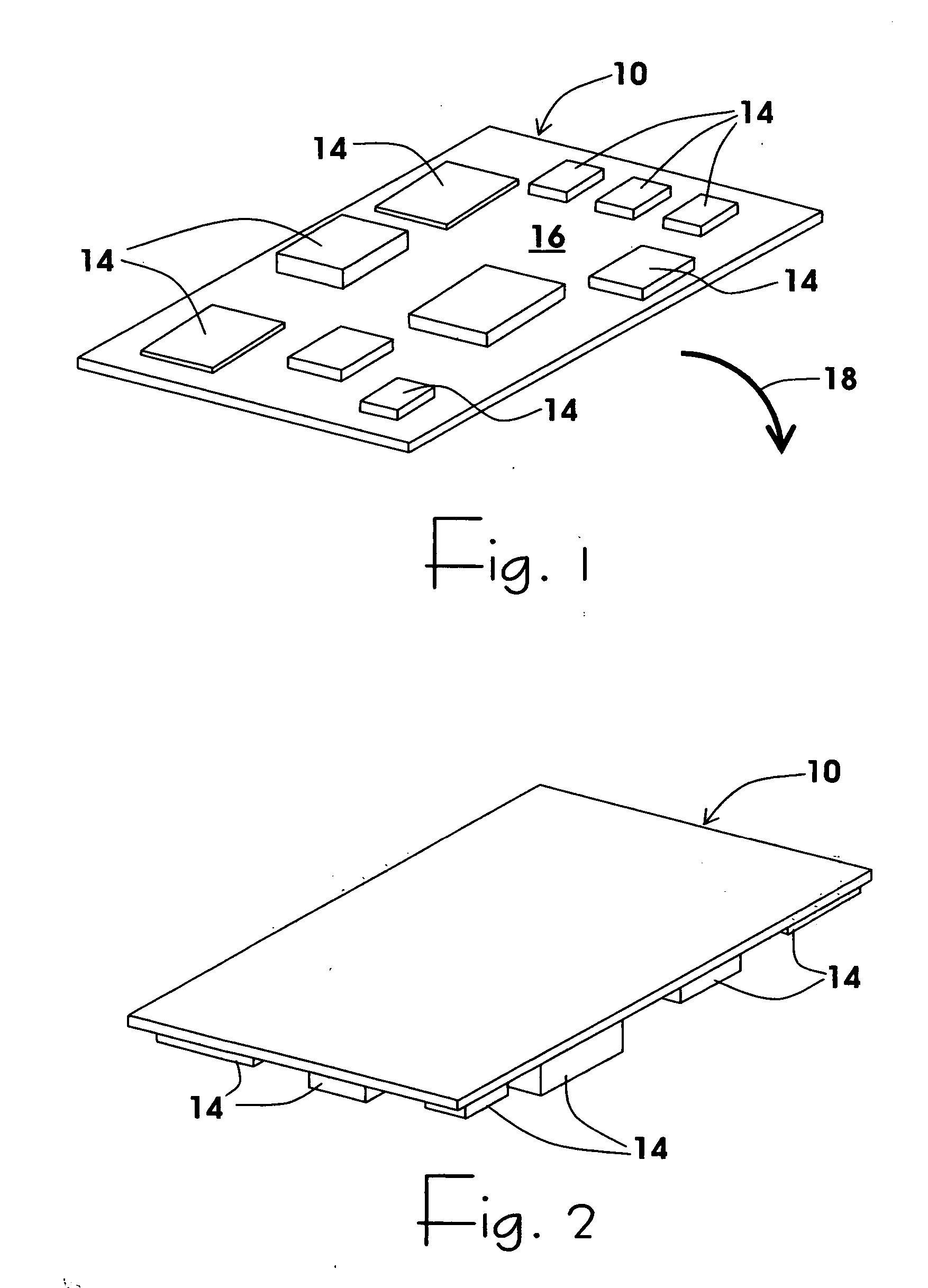
[0055] What is now presented is a method for using a pin array support that is trained on a bottom side populated circuit board in which the pins extend to touch the bottom side of the board where they are then locked in place.

[0056] Referring now to FIG. 1, what is illustrated is a training board 10 having a number of components 14 populated on the topside 16 of the printed circuit board. Upon population of the components on top of the to-be double-sided printed circuit training board, it is inverted or flipped over as illustrated by arrow 18 so as to achieve the orientation illustrated in FIG. 2 with components 14 pointed in a downward direction. The result is an irregular or contoured underside. It will be appreciated that being able to support such circuit board that is bottom side populated to provide a flat top surface requires a support structure that can be configured to accommodate and support the various components on the underneath side of the circuit board as well as th...


PUM


Abstract

Pin supported printed circuit boards are provided with torsion spring locking assemblies in which torsion springs surround the pins and are captured at one end and have free ends that are deflected, causing a tight grip onto the pins. The result is a pin locking mechanism that is inexpensive and robust due to the elongated contact of the spring with the pin that firmly locks the pin in place, with the extended spring contact protecting the pins against abrading and scoring while providing exceptional locking force.

Description

RELATED APPLICATIONS [0001] This Application claims benefit of U.S. Provisional Patent Application No. 60 / 675,999 filed Apr. 29, 2005, entitled Apparatus to Support a Circuit Board, the contents of which are incorporated herein by reference.FIELD OF THE INVENTION [0002] This invention relates to the support of work pieces and more particularly to a locking mechanism for locking pins used to support a work piece having an irregular contour. BACKGROUND OF THE INVENTION [0003] As described in U.S. Pat. No. 5,984,293, there is a requirement for a universal fixture for supporting printed circuit board assemblies during stencil printing, pick-and-place processing and other printed circuit board assembly processes including the dispensing of conductive adhesives on the top surfaces of printed circuit boards. These particular operations suffer from printed circuit board flexure during manufacture. For instance, with current technologies, printed circuit boards must be maintained flat to wit...

Claims


Application Information

Patent Timeline
Patent Type & Authority Applications(United States)
IPC IPC(8): B25B5/16
CPCH05K13/0069
Inventor ERDMANN, GUNTER
Owner ERDMANN GUNTER
Why Eureka
Try Eureka