Charge pump

a technology of charge pump and discharge pump, which is applied in the direction of dc-dc conversion, power conversion system, instruments, etc., can solve the problems of high production cost and increase the cost of external capacitors, and achieve the effect of significantly reducing production cos

Active Publication Date: 2006-11-02
NOVATEK MICROELECTRONICS CORP
View PDF5 Cites 141 Cited by
  • Summary
  • Abstract
  • Description
  • Claims
  • Application Information

AI Technical Summary

Benefits of technology

[0014] From the above described it can be seen that the internal capacitors in the pump unit of the present invention are dynamically coupled. Therefore, the internal capacitors can be shared in a charge pump to provide at least a first output voltage and a second output voltage. In this way, the number of capacitor components and the production cost can be significantly reduced.

Problems solved by technology

For an integrated circuit, capacitor components, for example the capacitors 105 and 106 in FIG. 1 and the capacitors 305 and 306 in FIG. 3, usually occupy a lot of space, which leads to a high production cost.
Even if the capacitor components are moved outside of the IC, i.e. the capacitor components become external components of the IC, the external capacitors would still increase the cost.

Method used


Image

  • Charge pump
  • Charge pump
  • Charge pump

Examples


Embodiment Construction

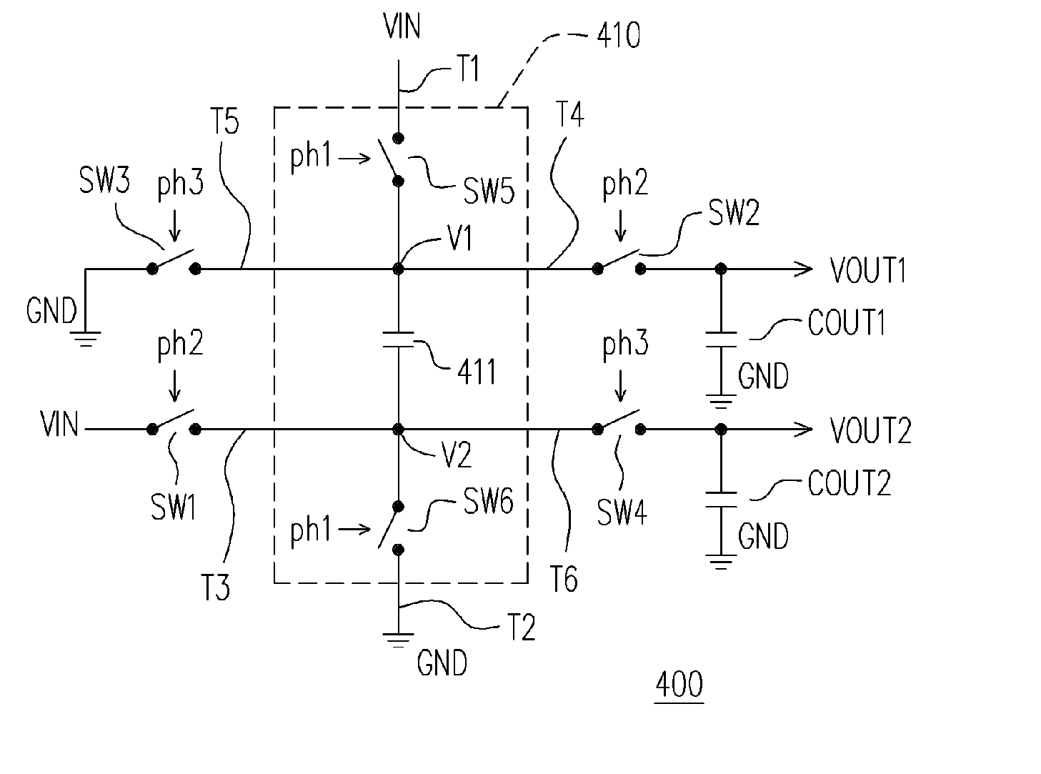
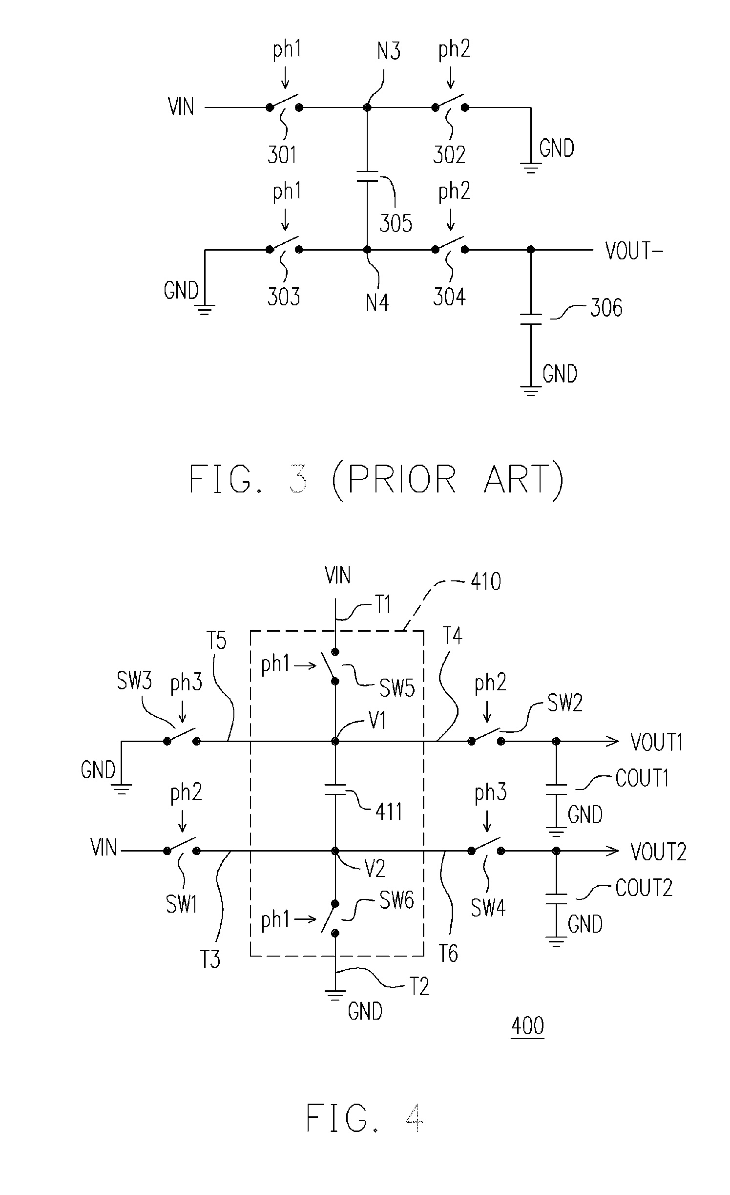
[0025]FIG. 4 is a schematic circuit drawing of a charge pump according to an embodiment of the present invention. FIG. 5 is a schematic chart showing the control signal timings of the charge pump in FIG. 4. Referring to FIG. 4 and FIG. 5, a charge pump 400 is connected to an input voltage VIN for outputting a first output voltage VOUT1 and a second output voltage VOUT2. The charge pump 400 includes, for example, a pump unit 410, a first switch SW1, a second switch SW2, a third switch SW3, a fourth switch SW4, a first output capacitor COUT1 and a second output capacitor COUT2.

[0026] The first end T1 of the pump unit 410 is coupled to the input voltage VIN and the second end T2 thereof is coupled to the first voltage (in the embodiment, the first voltage is the ground voltage GND). The pump unit 410 in the embodiment includes, for example, an internal capacitor 411, a fifth switch SW5 and a sixth switch SW6. The first end of the fifth switch SW5 is the first end T1 of the pump unit 4...


PUM


Abstract

A charge pump used for producing at least a first output voltage and a second output voltage according to an input voltage is disclosed. The charge pump includes a pump unit, the first to fourth switches, a first output capacitor and a second output capacitor. During a first period, the input voltage and the first voltage, through the first end and the second end of the pump unit respectively, charge at least an internal capacitor. During a second period, the internal capacitor, based on the second voltage level of the first switch and though the second switch, provides the first output capacitor with charges for producing the first output voltage. Finally, during the third period, the internal capacitor, based on the third voltage level of the third switch and though the fourth switch, provides the second output capacitor with charges for producing the second output voltage.

Description

CROSS-REFERENCE TO RELATED APPLICATION [0001] This application claims the priority benefit of Taiwan application serial no. 94113628, filed on Apr. 28, 2005. All disclosure of the Taiwan application is incorporated herein by reference. BACKGROUND OF THE INVENTION [0002] 1. Field of Invention [0003] The present invention relates to a charge pump, and particularly to a charge pump with fewer capacitors and capable of providing at least a first output voltage and a second output voltage. [0004] 2. Description of the Related Art [0005] In an electronic circuit, a plurality of charge pump circuits are usually required for providing various power voltage levels. If, for example, an electronic circuit needs a voltage of two times as high as the power voltage level and a negative voltage of the power voltage level, there must be a charge pump circuit with a voltage doubling circuit (as shown in FIG. 1) to provide a double positive voltage level VOUT+ and another charge pump circuit with a n...

Claims


Application Information

Patent Timeline
Patent Type & Authority Applications(United States)
IPC IPC(8): G05F1/10
CPCH02M3/07
Inventor YEN, CHIH-JENHSU, LIANG-KUEI
Owner NOVATEK MICROELECTRONICS CORP
Why Eureka
Try Eureka