
Lens transfer device improved in assemblability

Inactive Publication Date: 2006-11-02
SAMSUNG ELECTRO MECHANICS CO LTD
View PDF1 Cites 54 Cited by
  • Summary
  • Abstract
  • Description
  • Claims
  • Application Information

AI Technical Summary

Benefits of technology

[0025] An object of the present invention is to provide a lens transfer device improved in assemblability, in which a barrel holder and a leaf spring can be easily assembled with each other and an assembling work for the leaf spring and the case is not required.
[0026] Another object of the present invention is to provide a lens transfer device improved in assemblability, which can improve an yield by preventing damage of a leaf spring, which may be caused during an assembling process, and can easily control tolerance in a direction of an optical axis by simply adjusting a relative position between the leaf spring and the barrel holder.
[0027] Still another object of the present invention is to provide a lens transfer device improved in assemblability, which employs two leaf springs so that no guide unit is necessary.

Problems solved by technology

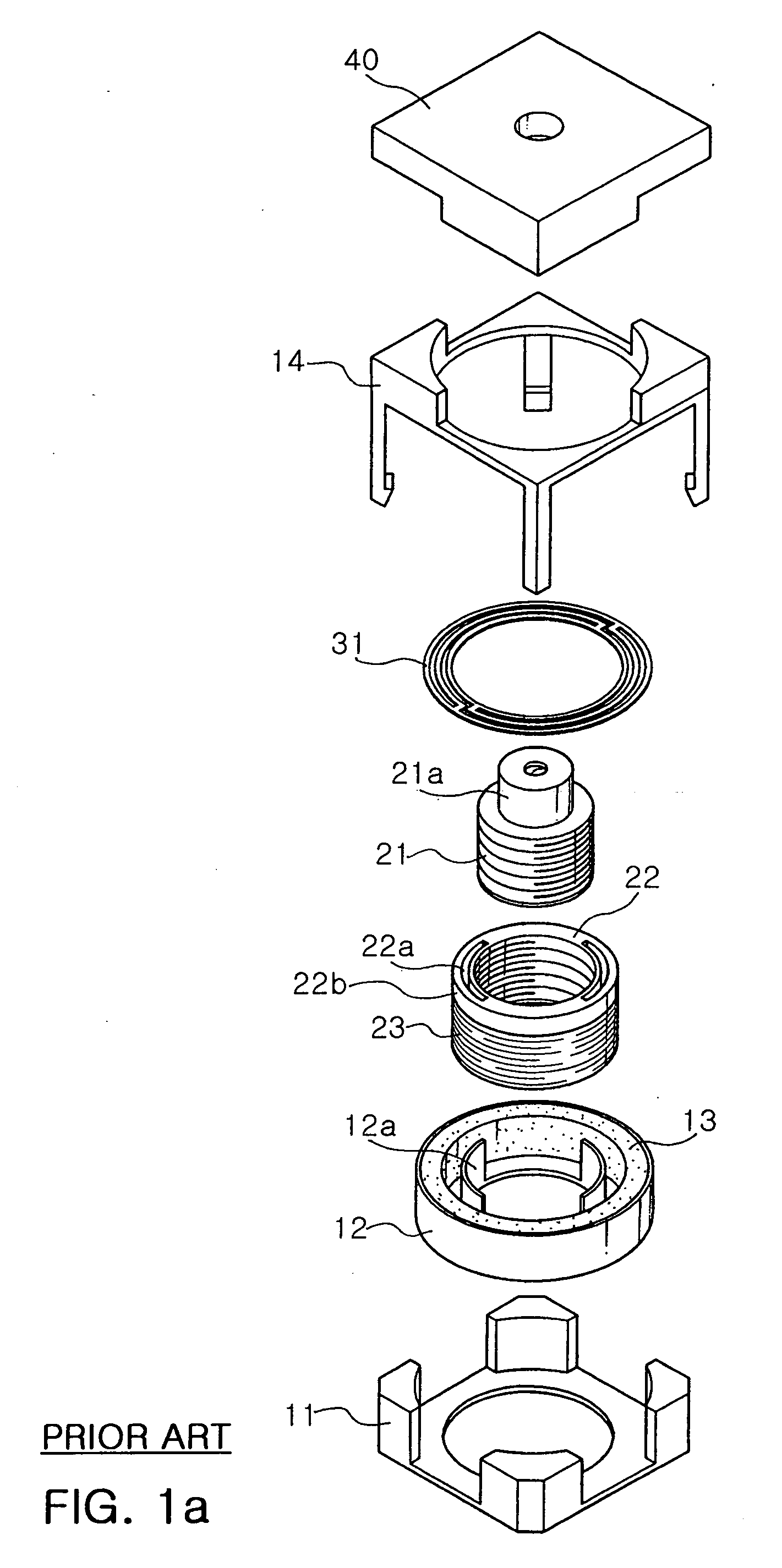
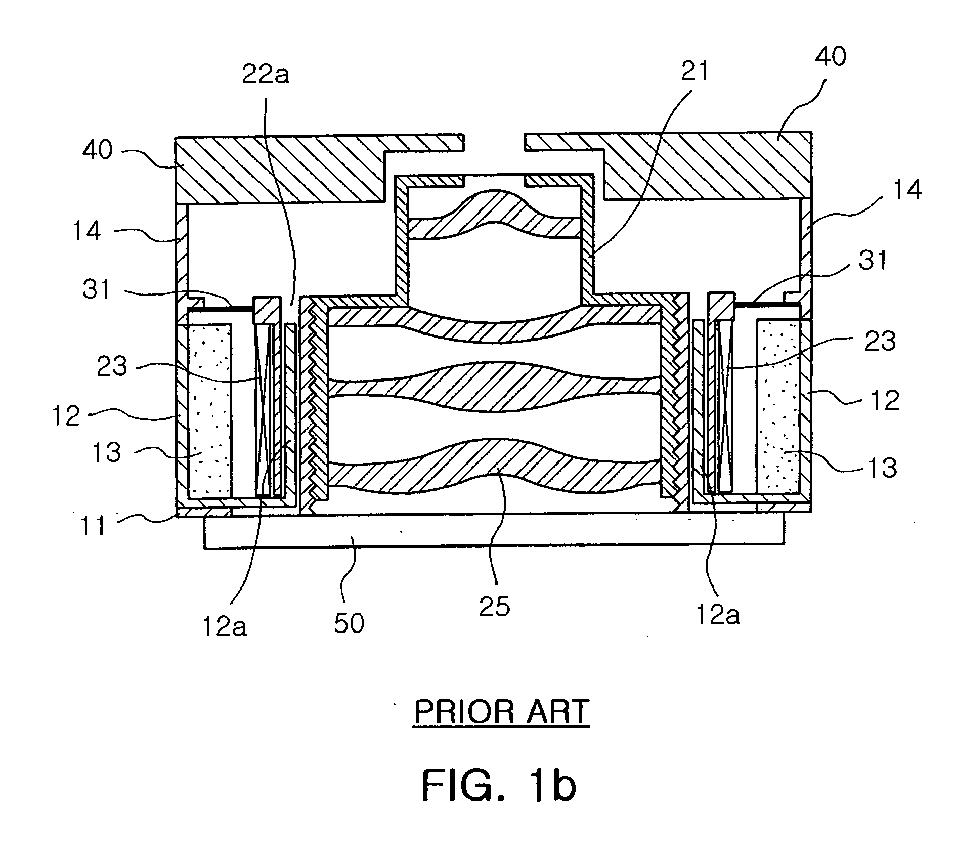
However, the focusing device of the related art has the following problems.
Furthermore, when the lens barrel 21 moves in the direction of the optical axis, the movement may not be accurately realized.

Method used


Image

  • Lens transfer device improved in assemblability
  • Lens transfer device improved in assemblability
  • Lens transfer device improved in assemblability

Examples


first embodiment

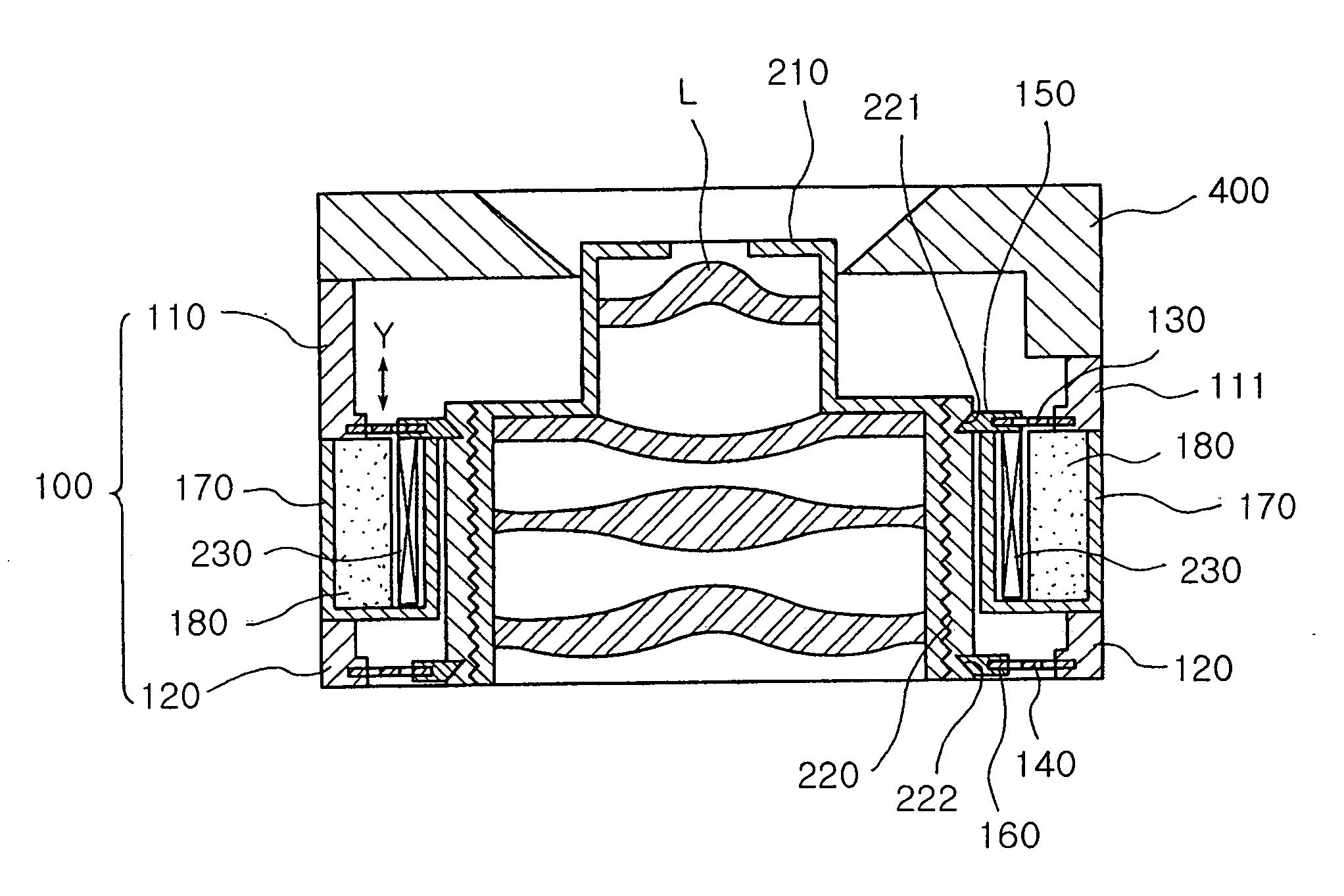
[0086] In the case of the first embodiment, the transfer force is applied to the holder connector 150 adhered to the coil 230, by which the leaf spring 130 connected to the holder connector 150 is elastically deformed to provide the displacement required for the reciprocation motion of the barrel holder 220.

[0087] That is, by the current applied to the coil 230, the barrel holder 220 moves in the direction of the optical axis Y of FIG. 2B. As a result, the lens L installed in the lens barrel 210 mounted in the barrel holder 220 moves. Therefore, a relative distance between an image sensor (not shown) and the lens L varies to adjust the focusing and zooming.

[0088] At this point, by the balance between the elastic forces applied by the first and second leaf springs 130 and 140, the movement in the direction of the optical axis can be accurately realized even when there is no special guide unit.

second embodiment

[0089] Meanwhile, in the case of the second embodiment, as shown in FIG. 5b, when the current is applied to the coil 230, the barrel holder 220 around which the coil is wound transfers. At this point, the transfer in the direction of the optical axis Y is reliably realized by the guide plates 172 inserted in the guide holes 225.

[0090] According to the present invention, since the leaf spring is integrally formed with the case, there is no need for a process for assembling the leaf spring with the case. In addition, since the holder connector having the protrusions is associated with the leaf spring and the barrel holder is provided with the grooves in which the protrusions is snap-fitted, the process for assembling the leaf spring and the barrel holder can be simplified, thereby improving the assemblability.

[0091] Also, unlike the related art where the leaf spring is forcedly fitted, since the leaf spring is snap-fitted to the barrel holder, the damage or breakage of the leaf sprin...


PUM


Abstract

A lens transfer device improved in assemblability. The lens transfer device includes a barrel holder. An upper case includes a first holder connector having a protrusion snap-fitted into a groove formed on an upper-outer circumference of the barrel holder, a first leaf spring connected to an outer circumferential portion of the first holder connector, and a first body connected to an outer circumferential portion of the first leaf spring. A lower includes a second holder connector having a protrusion snap-fitted into a groove formed on a lower-outer circumference of the barrel holder, a second leaf spring connected to an outer circumferential portion of the second holder connector, and a second body connected to the second leaf spring. A yoke is provided to mount a magnet assembly and mounted on the lower case. A coil is installed and spaced by a predetermined gap from the magnet assembly.

Description

RELATED APPLICATION [0001] The present application is based on, and claims priority from, Korean Application Number 2005-31950, filed Apr. 18, 2005, the disclosure of which is hereby incorporated by reference herein in its entirety. BACKGROUND OF THE INVENTION [0002] 1. Field of the Invention [0003] The present invention relates to a lens transfer device employing a voice coil motor, and more particularly, to a lens transfer device that is improved in assemblability by allowing a leaf spring to be snap-fitted to a barrel holder. [0004] 2. Description of the Related Art [0005] Generally, a camera has a plurality of lenses and a focal length of the camera is adjusted by moving the lenses. In recent years, a mobile phone with a camera function has come into the market. Therefore, it becomes possible to take a still image or a moving picture using the mobile phone having the camera function. In order to take high resolution / definition images and moving pictures, the performance of the c...

Claims


Application Information

Patent Timeline
IPC IPC(8): G02B7/02
CPCG02B7/08G02B13/009G02B13/004H04N23/00
Inventor LEE, CHEONG HEEJEONG, HO SEOPBAIK, JAE HO
Owner SAMSUNG ELECTRO MECHANICS CO LTD
Learn More