Data reception apparatus and synchronizing signal detection method and program

a data reception and signal detection technology, applied in data rate detection arrangements, synchronous/start-stop systems, digital transmission, etc., can solve problems such as the inability of slaves to receive accurate data, and achieve the effect of accurate detection and obtaining baud ra

Inactive Publication Date: 2006-11-02
RENESAS ELECTRONICS CORP
View PDF8 Cites 32 Cited by
  • Summary
  • Abstract
  • Description
  • Claims
  • Application Information

AI Technical Summary

Benefits of technology

[0016] According to the present invention, the beginning of a frame is found by calculating the ratio between a first pulse w

Problems solved by technology

Meanwhile, when a slave on that the baud rate is to be measured starts up, the first signal that it receives is not always the Synch Break Field because the master that transmits the signal to the slave does no

Method used


Image

  • Data reception apparatus and synchronizing signal detection method and program
  • Data reception apparatus and synchronizing signal detection method and program
  • Data reception apparatus and synchronizing signal detection method and program

Examples


embodiment 1

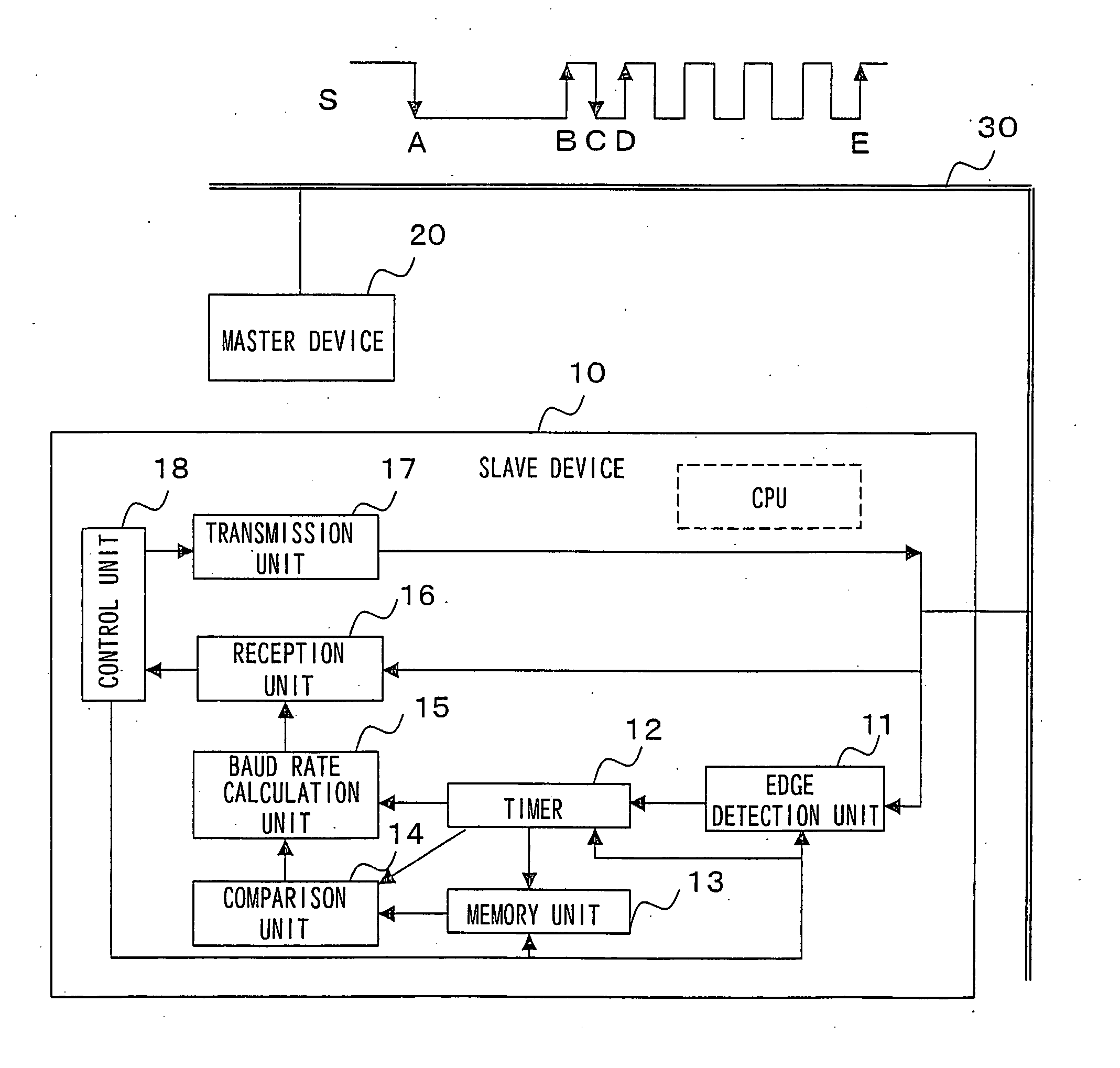
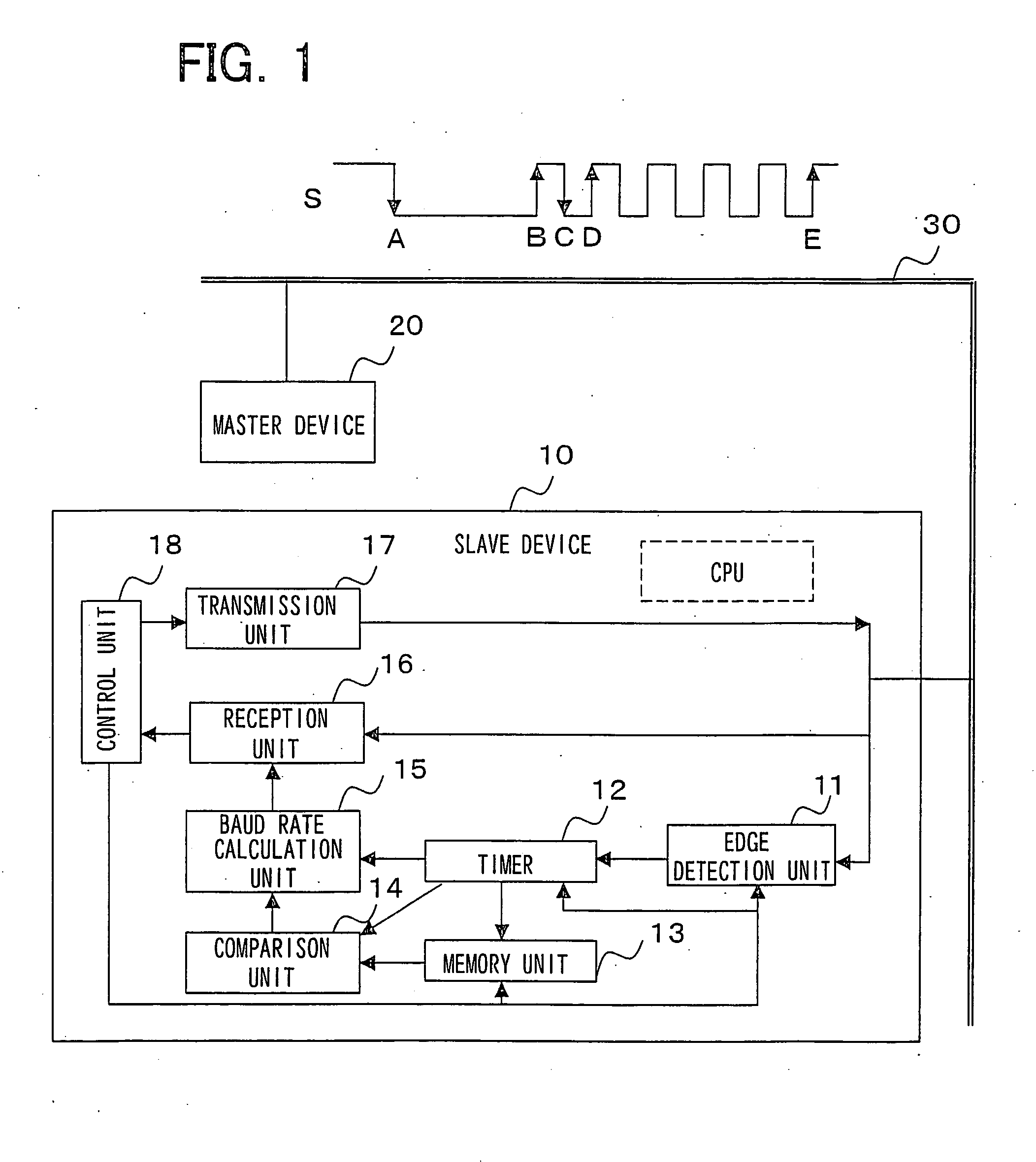
[0021]FIG. 1 is a block diagram illustrating the structure of a communication system relating to a first embodiment of the present invention. In FIG. 1, the communication system is structured so that a slave device 10 and a master device 20 are connected to a bus 30. First, the master device 20 transmits a binary level signal S on the bus 30. The slave device 10 receives the binary level signal S, and then a predetermined binary level signal is transmitted / received between the slave device 10 and the master device 20 as necessary.

[0022] The slave device 10 comprises an edge detection unit 11, a timer 12, a memory unit 13, a comparison unit 14, a baud rate calculation unit 15, a reception unit 16, a transmission unit 17, and a control unit 18. Further, a CPU and a program may be implemented in the slave device 10, and each of the above or some of the above may be operated by having the CPU execute the program.

[0023] The edge detection unit 11 receives the binary level signal S that...

embodiment 2

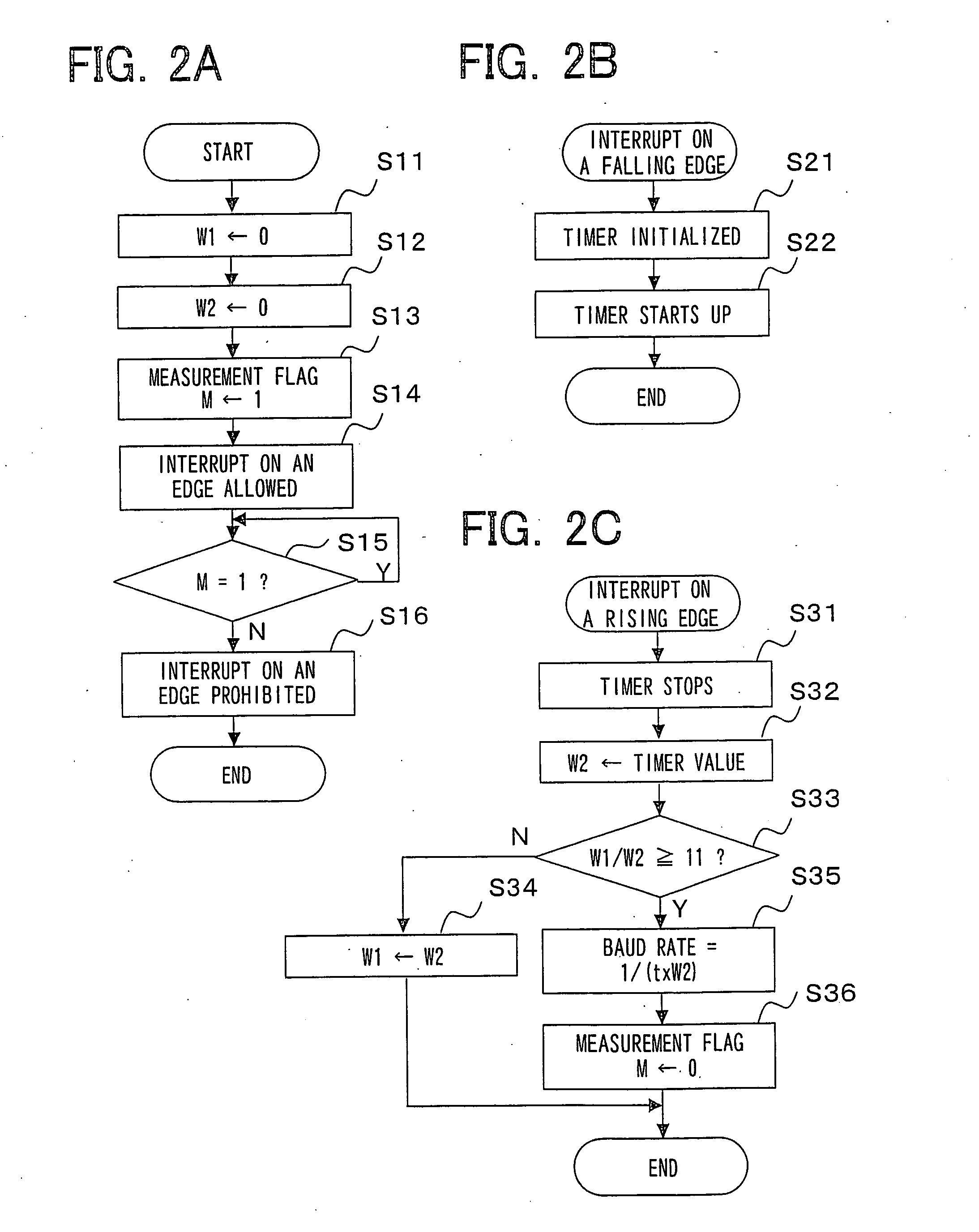
[0036]FIGS. 3A, 3B and 3C show flowcharts illustrating the operation of a slave device relating to the second embodiment of the present invention. FIG. 3A show the flowchart of a main processing, FIG. 3B shows the flowchart of an interrupt processing on a falling edge of the binary level signal S, and FIG. 3C shows the flowchart of an interrupt processing on a rising edge of the binary level signal S. In the first embodiment, the timer starts up at a falling interrupt and stops at a rising interrupt, however, in the second embodiment, the timer continues to operate, counts the lapse of time and derives the pulse width.

[0037] First, the main processing in FIG. 3A will be described. When a synchronizing signal detection process starts in the main processing, as an initialization process, variables W1 and W2 that store the pulse width are set to 0 (a step S41), variables T1 and T2 that store the timer value are set to 0 (a step S42), and the measurement flag M indicating it is in the ...


PUM


Abstract

To detect the Synch Field accurately and find the beginning of a frame in order to calculate the baud rate. A slave device is connected to a bus and receives a binary level signal on the bus transmitted from a master device. The slave device detects the signal level of the binary level signal and calculates the time of a first period and a second period when the binary level signal is at a low level, which respectively exist before and after the binary level signal is at a high level. When the ratio of the first period to the second period is not less than 11, the binary level signal that the device continues to receive after the second period is identified as the Synch Field. From the reciprocal number of the second period, the baud rate for the slave device to receive the binary level signal is calculated.

Description

FIELD OF THE INVENTION [0001] The present invention relates to a data reception apparatus and synchronizing signal detection method and program, and particularly to a data reception apparatus that receives a binary level signal on a bus, and a method and a program for detecting a synchronizing signal in the binary level signal. BACKGROUND OF THE INVENTION [0002] In recent years, the demand for automotive LAN has increased and the most suitable network for each application has been utilized. LIN (Local Interconnect Network) is a communication protocol for automotive LAN. It is a serial communication protocol based on a master-slave structure and is mainly used in simple systems such as a body system. In the LIN communication protocol, there are a Synch Break Field that indicates the beginning of a frame and a field of a synchronizing signal called Synch Field that follows the Synch Break Field, and by transmitting the Synch Field from the master to the slave, the slave receives data ...

Claims


Application Information

Patent Timeline
IPC IPC(8): H04L25/49
CPCH04L25/0262H04L7/0331
Inventor TACHI, NOBUYUKI
Owner RENESAS ELECTRONICS CORP
Why Eureka
Try Eureka