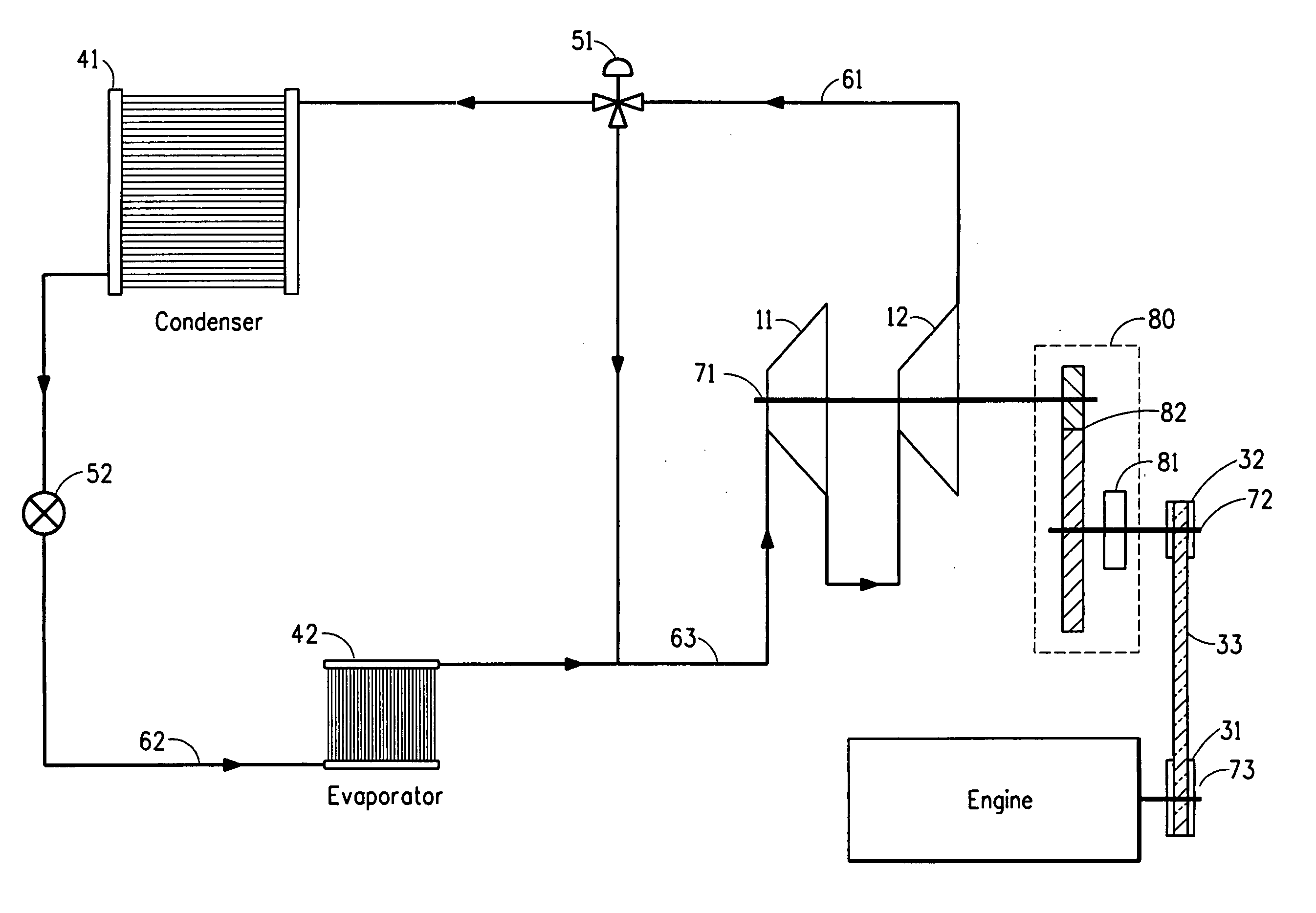
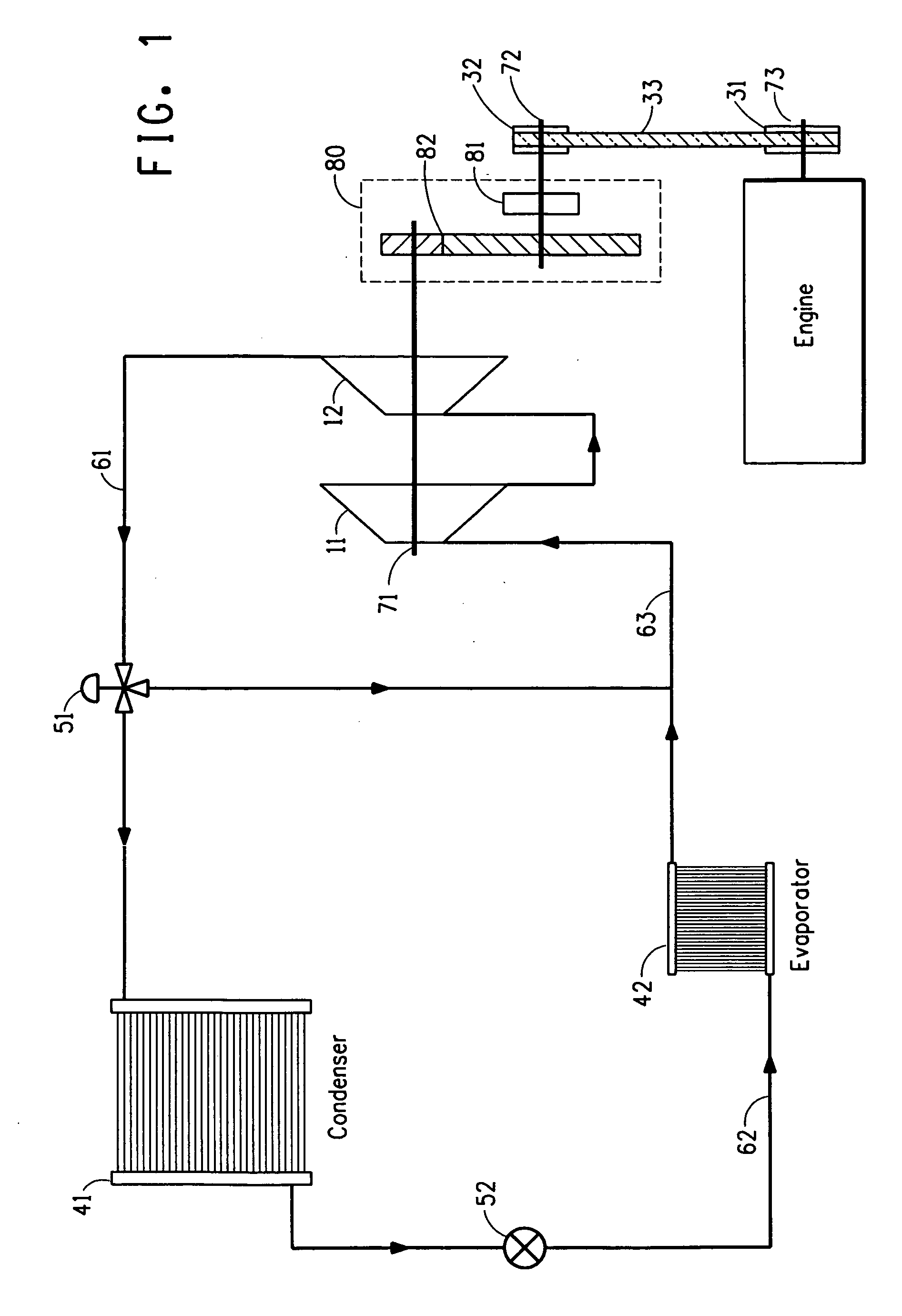
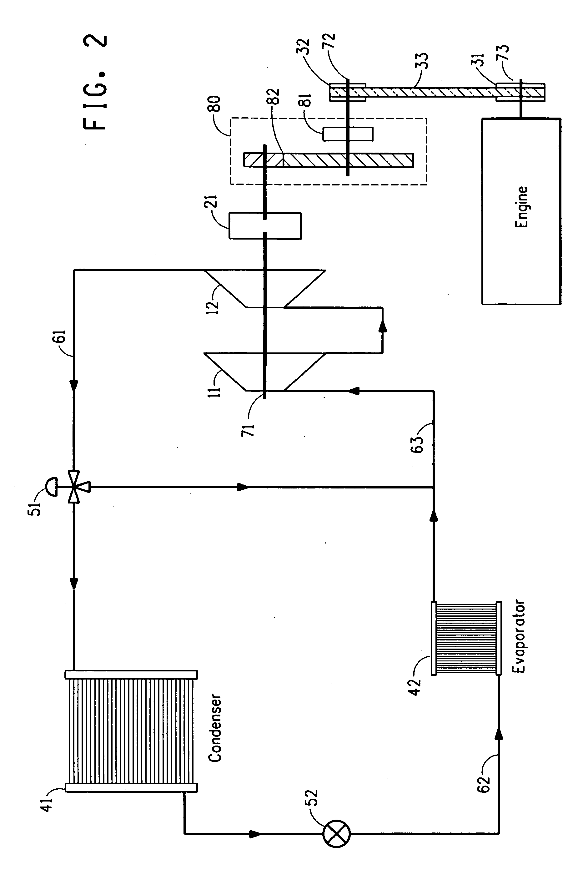
Cooling apparatus powered by a ratioed gear drive assembly

a technology of gear drive and cooling apparatus, which is applied in vehicle heating/cooling devices, piston pumps, vehicle components, etc., can solve the problem that the power requirements of a mini-centrifugal compressor are not easily m

Inactive Publication Date: 2006-11-02
EI DU PONT DE NEMOURS & CO
View PDF5 Cites 71 Cited by
  • Summary
  • Abstract
  • Description
  • Claims
  • Application Information

AI Technical Summary

Benefits of technology

[0014] In particular, the present invention relates to a refrigeration or air-conditioning apparatus comprising a compressor driven by a ratioed gear drive assembly coupled to an internal combustion engine. By making use of the present invention, the ratioed gear drive with optional ratioed belt drive provides the energy necessary with the required increase in rotational speed to provide optimum operation of the refrigeration or air-conditioning apparatus.

Problems solved by technology

Moreover, The power requirements for a mini-centrifugal compressor are not easily met in the present design for automobile engines.

Method used


Image

  • Cooling apparatus powered by a ratioed gear drive assembly
  • Cooling apparatus powered by a ratioed gear drive assembly
  • Cooling apparatus powered by a ratioed gear drive assembly

Examples


example

[0081] The table below shows theoretical tip speed and impeller diameter for a system using PEIK (perfluoroethylisopropylketone) as refrigerant to produce cooling capacity of approximately 1.5 tons at an impeller speed of 40,000 rpm. The conditions assumed for this example are:

Evaporator temperature 40.0° F. (4.4° C.)Condenser temperature110.0° F. (43.3° C.)Liquid subcool temperature 10.0° F. (5.5° C.)Return gas temperature 75.0° F. (23.8° C.)Compressor efficiency is 80%

[0082] These are typical conditions under which small turbine centrifugal compressors perform. Table 1 below shows the enthalpy of the refrigerant gas as it leaves the evaporator, (H Evaporator Out), the enthalpy of the refrigerant gas as in enters condenser (H Condenser In), the change in enthalpy between the evaporator and compressor, (Delta Hi), and the change in enthalpy between the evaporator and compressor multiplied by 0.8 to account for a compressor efficiency of 80%. The table below also shows theoretical ...


PUM


Abstract

The present invention relates to a cooling apparatus comprising a refrigeration or air-conditioning apparatus. In particular the present invention relates to refrigeration or air-conditioning apparatus utilizing a mini-centrifugal compressor with rotational power provided by a ratioed gear drive assembly coupled to an internal combustion engine.

Description

CROSS REFERENCE(S) TO RELATED APPLICATION(S) [0001] This application claims the priority benefit of U.S. Provisional Application 60 / 663,924, filed Mar. 21, 2005.BACKGROUND OF THE INVENTION [0002] 1. Field of the Invention [0003] The present invention relates to refrigeration and air-conditioning apparatus. In particular the present invention relates to mobile refrigeration and air-conditioning apparatus utilizing a mini-centrifugal compressor with rotational power provided by a ratioed gear drive assembly. [0004] 2. Description of Related Art [0005] The refrigeration industry has been working for the past few decades to find replacement refrigerants for the ozone depleting chlorofluorocarbons (CFCs) and hydrochlorofluorocarbons (HCFCs) being phased out as a result of the Montreal Protocol. The solution for most refrigerant producers has been the commercialization of hydrofluorocarbon (HFC) refrigerants. The new HFC refrigerants, HFC-134a being the most widely used at this time, have...

Claims


Application Information

Patent Timeline
Patent Type & Authority Applications(United States)
IPC IPC(8): F04B35/00
CPCB60H1/3223B60H1/3222
Inventor LECK, THOMAS J.BIVENS, DONALD BERNARDZHAO, FUQINROHACEK, MIROSLAVMATHUR, PAUL K.
Owner EI DU PONT DE NEMOURS & CO
Why Eureka
Try Eureka