Goal detector for detection of an object passing a goal plane

Inactive Publication Date: 2006-11-02
FRAUNHOFER GESELLSCHAFT ZUR FOERDERUNG DER ANGEWANDTEN FORSCHUNG EV
View PDF8 Cites 11 Cited by
  • Summary
  • Abstract
  • Description
  • Claims
  • Application Information

AI Technical Summary

Benefits of technology

[0022] It is generally preferred that at least some of and possibly all of the pairs of antennas are arranged on the goal delimiting the flat target plane, the goal normally consisting of two substantially vertical goalposts and a horizontal crossbar extending there between. The pairs of antennas may be arranged on the crossbar as described, on the goalposts or distributed on both the crossbar and the two goalposts. The pairs of antennas arranged on the goal are preferably embedded within the goalposts and/or the horizontal crossbar so that a substantially smooth surface of the goal is preserved.
[0023] It is furthermore advantageous that the system of the invention comprises at least one stationary calibrator device emitting waves receivable by the antennas, arranged in the flat target plane to provide a calibration signal for the system. Thereby, a temporary or constant calibration routine may be performed by the system during use so as to compensate for changes in the position, orientation or other features of the antennas that are influential on their performance and output. The one or more stationary emitters are advantageously arr

Problems solved by technology

However, this may be very difficult to determine correctly in situations where the ball is returned quickly and has only just passed, or not passed, the goal plane, and it is particularly difficult if the referee is positioned unsuitably with respect to the goal plane or is engaged in other activity of the match.
Video camera may also be used to monitor the goal planes, but the spatial and temporal resolution of video cameras are often not sufficient to provide the necessary information in cases of doubt.
However, the determination of the passage of the goal plane is a very delicate matter, both because it may be decisive for the outcome of the sports match and because the distances are small and the velocity of the object often very high, so that a position determining system to provide a reliable determination of whether the object has passed the goal plane must be very precise in the determination of the position and at the same time have a very high update rate of the position determination.
The object may e.g. move with 72 km/h or 20 m/s, which means that an update rate of 1/100 s will add an uncertainty of 20 cm to the determin

Method used


Image

  • Goal detector for detection of an object passing a goal plane
  • Goal detector for detection of an object passing a goal plane
  • Goal detector for detection of an object passing a goal plane

Examples


Embodiment Construction

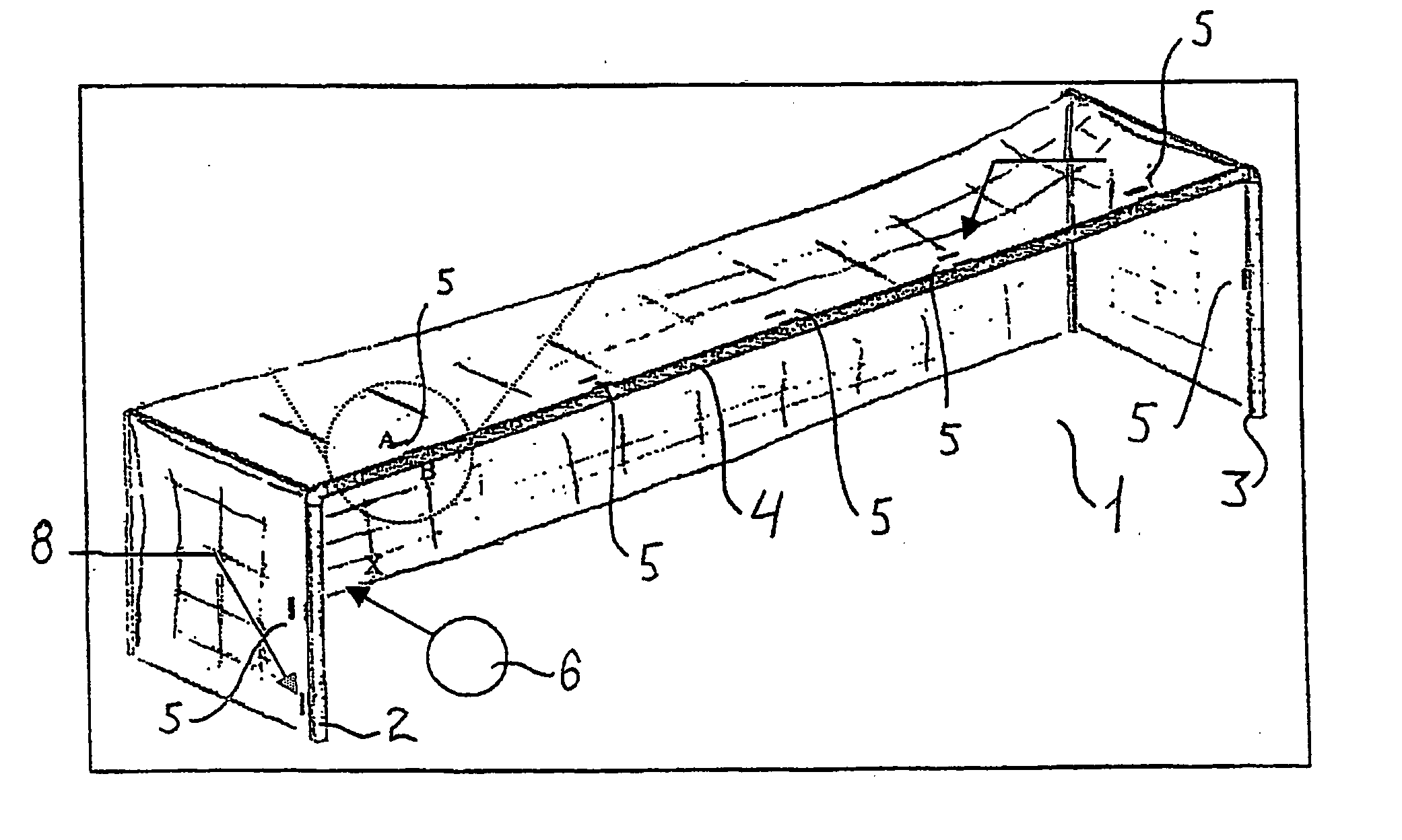
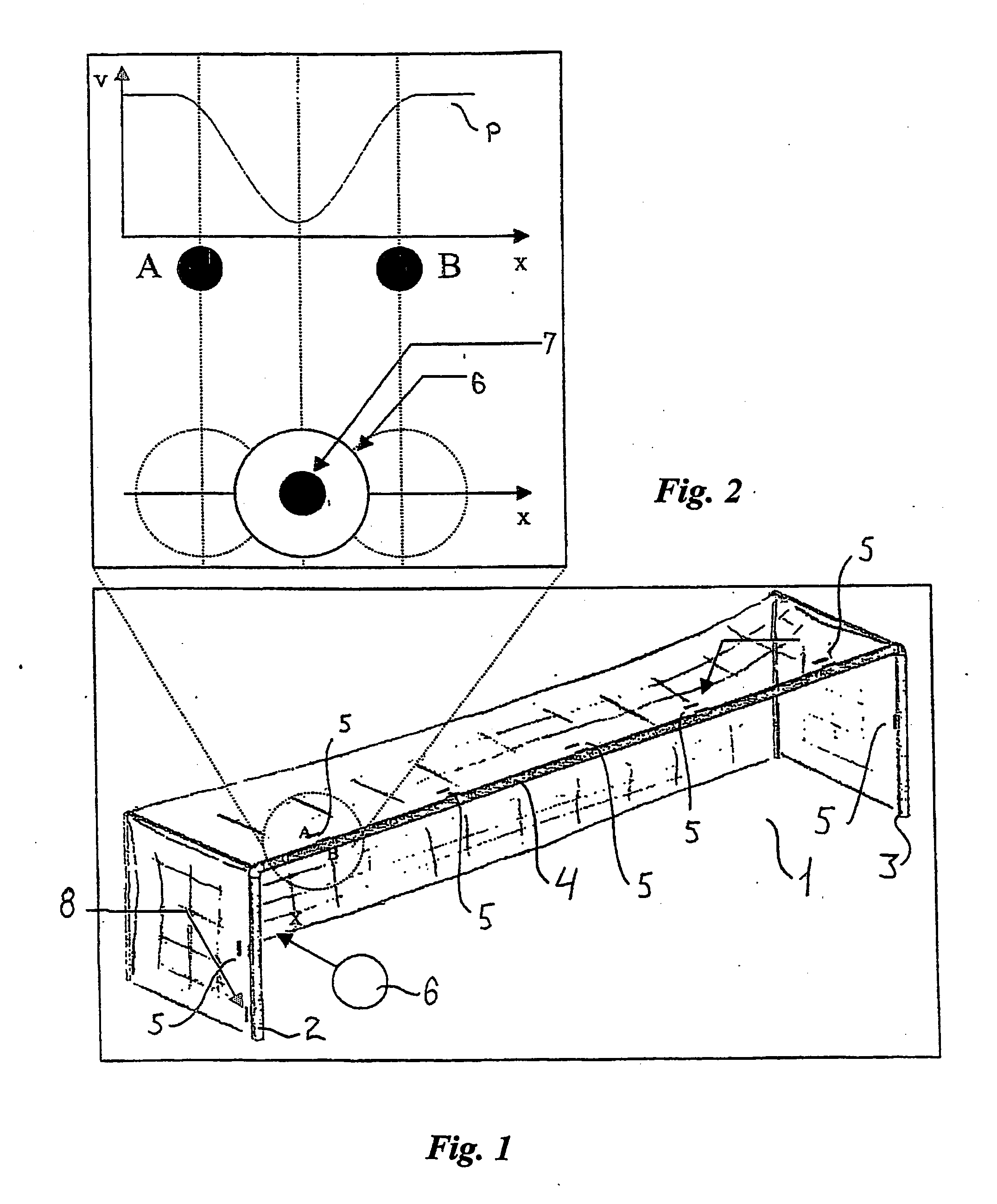
[0032] A football goal 1 is shown in FIG. 1 having a left goalpost 2, a right goalpost 3 and a horizontal crossbar 4 there between. The goal 1 is placed on a sports field with the posts 2, 3 placed on the centre of the goal line (not shown) and the crossbar 4 being parallel with and directly above the goal line in accordance with the laws of FIFA, so that the goal line, the posts 2, 3 and the cross bar 4 delimits a flat target plane.

[0033] Five pairs of antennas 5 are arranged equidistantly on the crossbar 4 and two pairs 5 are arranged each on one post 2, 3. Each pair of antennas 5 comprises two identical antennas A, B that are arranged parallel with a displacement only in the direction perpendicular to the target plane. The antennas A, B are arranged so that the midway position is situated precisely half the diameter of the ball from the back edge of the goal line. A goal is scored when the whole of the ball pass over the goal line, between the goalposts 2, 3 and under the cross ...


PUM


Abstract

A system is disclosed for detection of whether a movable object, such as a sports object, e.g. a football or an ice hockey puck, has passed a flat plane in space, such as a goal plane defined e.g. as a vertical plane extending from a goal line or a horizontal plane defined by the upper rim of the basketball basket The system comprises a plurality of pairs of antennas arranged along the periphery of the flat target plane, the two antennas of each of said pairs being arranged with a mutual displacement in the direction perpendicularly to the flat target plane, radio wave emitter means arranged in the movable object and/or each antenna, and means for receiving the radio waves from the radio wave emitter means and provide an output accordingly arranged in each antenna and/or in the movable object, the system further comprising processing means to receive and process said output together with a predetermined set of conditions and providing a resulting output if the set of conditions are fulfilled so as to determine whether the movable object passes the flat target plane.

Description

[0001] The present invention relates to a system for detection of whether a movable object, such as a sports object, e.g. a football or an ice hockey puck, has passed a flat plane in space, such as a goal plane defined e.g. as a vertical plane extending from a goal line or a horizontal plane defined by the upper rim of the basketball basket. BACKGROUND [0002] Traditionally, the referee or referees of a sports match decides from visual observation whether or not the ball has passed the goal plane. However, this may be very difficult to determine correctly in situations where the ball is returned quickly and has only just passed, or not passed, the goal plane, and it is particularly difficult if the referee is positioned unsuitably with respect to the goal plane or is engaged in other activity of the match. Video camera may also be used to monitor the goal planes, but the spatial and temporal resolution of video cameras are often not sufficient to provide the necessary information in ...

Claims


Application Information

Patent Timeline
IPC IPC(8): A63B63/00A63B43/00A63B71/06
CPCA63B24/0021A63B43/00A63B63/00A63B63/004A63B71/0605A63B2243/0045A63B2071/0611A63B2220/83A63B2220/89A63B2225/50A63B2243/0025A63B2024/0037A63B2102/24A63B71/06
Inventor PETERSEN, HANS
Owner FRAUNHOFER GESELLSCHAFT ZUR FOERDERUNG DER ANGEWANDTEN FORSCHUNG EV
Why Eureka
Try Eureka