Bone marrow harvesting set and bone marrow harvesting needle

a bone marrow and needle technology, applied in the field of bone marrow harvesting set and bone marrow harvesting needle, can solve the problems of high risk and unsuitable application, and achieve the effect of reducing the exposure to a non-aseptic environmen

Inactive Publication Date: 2006-11-02
JIMRO
View PDF20 Cites 34 Cited by
  • Summary
  • Abstract
  • Description
  • Claims
  • Application Information

AI Technical Summary

Benefits of technology

[0010] This invention has been made in light of the above described problems. Accordingly, the primary object of the invention is to provide a bone marrow harvesting set capable of harvesting bone marrow with minimized exposure to a non-aseptic environment.
[0011] The second object of the invention is to provide a bone marrow harvesting needle capable of harvesting bone marrow safely and quickly from a donor by the bone marrow perfusion method.

Problems solved by technology

In this method, however, since the quantity of bone marrow harvested from one site of a bone is as small as several ml, collecting a sufficient quantity of bone marrow requires a number of sites to be punctured; consequently, the method carries a high risk of allowing peripheral blood T cells to mix into the harvested bone marrow, and hence of causing GVHD, which necessitates immunosuppression.
The conventionally employed method in which a bone marrow puncture needle, equipped with a handle, is pressed into a bone by turning the handle by hand is not suitably applied to the bone marrow perfusion method, because the method using a handle does not easily allow the tip of the needle to reach the cavity accommodating bone marrow.

Method used


Image

  • Bone marrow harvesting set and bone marrow harvesting needle
  • Bone marrow harvesting set and bone marrow harvesting needle
  • Bone marrow harvesting set and bone marrow harvesting needle

Examples


embodiment 1

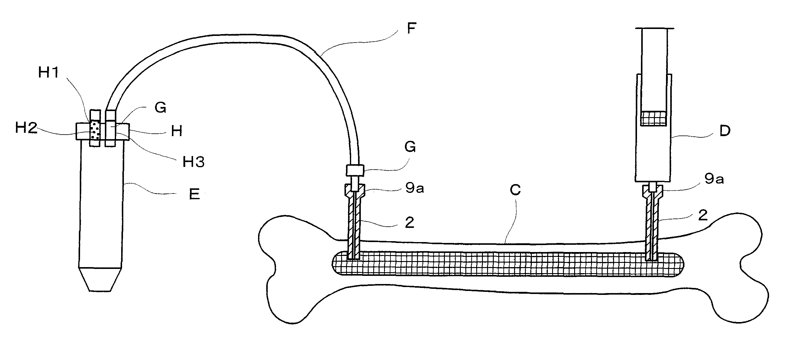
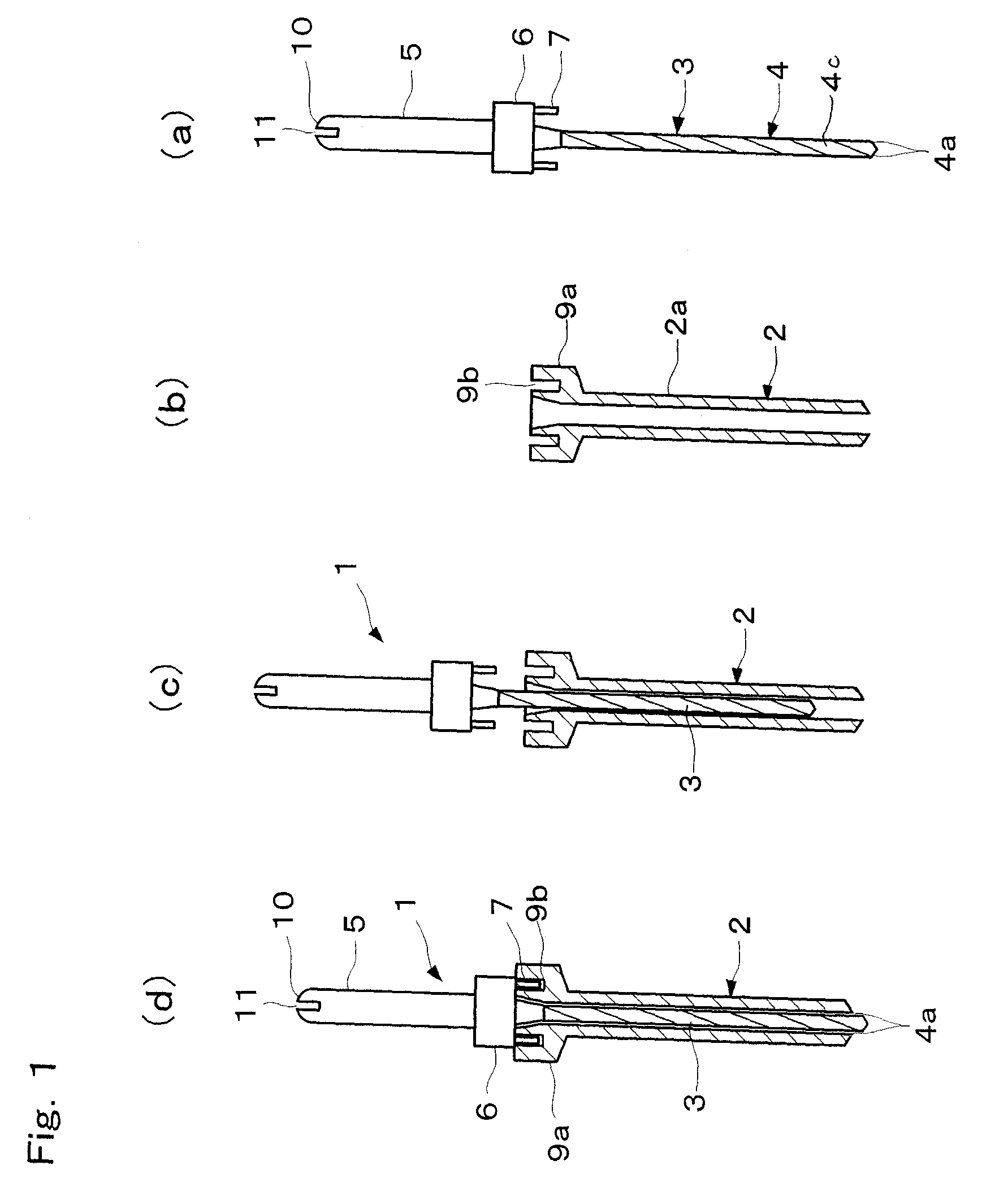
[0044] As shown in FIGS. 1(a) to 1(d), a bone marrow harvesting needle 1 consists of a mantle (outer needle) 2 and an inner needle 3 to be fitted into the mantle 2.

[0045] The inner needle 3 includes an inner needle body 4 and a holder 5, between the inner needle body 4 and the holder 5 an external flange 6 is formed, and on the external flange 6 a pair of pins 7 project to prevent free rotation of the mantle 2.

[0046] The inner needle body 4 forms a drill cutter having a cutting edge 4a at its tip. A helical groove 4c is formed throughout the full length of the inner needle body 4, and the tip of the inner needle body has a sharp cutting edge.

[0047] The mantle 2 includes a mantle body 2a and a fitting portion 9a, and the fitting portion 9a (e.g. lure lock type) is provided with a pair of pin holes 9b.

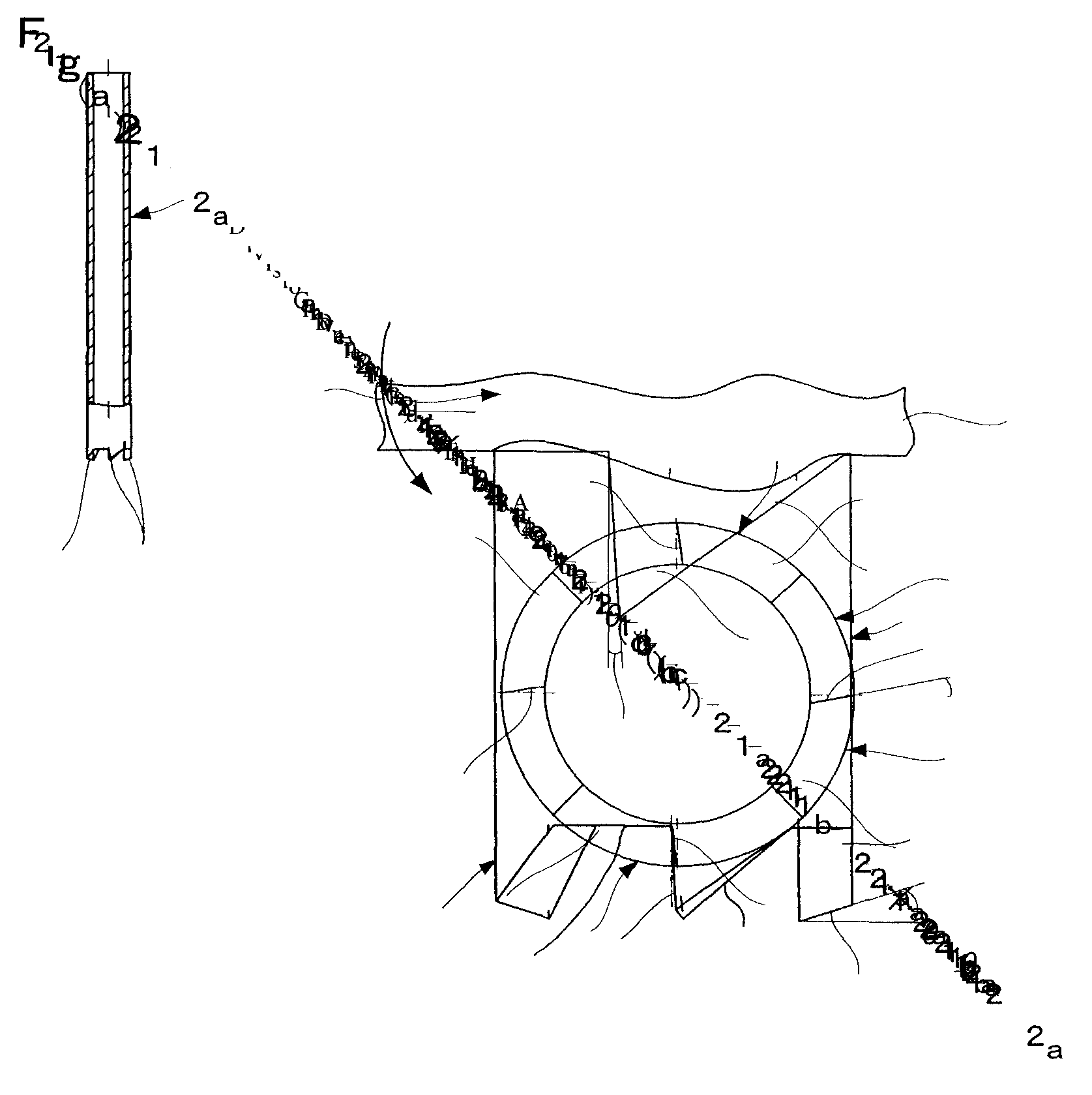
[0048] The mantle body 2a is cylindrically formed as shown in FIG. 2(a), and at the tip of the mantle body 2a a multiple of cutting edges 21 are formed at uniform intervals in a circ...

embodiment 2

[0064] FIGS. 8 to 13 illustrate a bone marrow harvesting set and a bone marrow harvesting needle of embodiment 2. The bone marrow harvesting needle 1 includes: a mantle 2, an inner needle 3 and co-rotation preventive mechanism 17.

[0065] As shown in FIGS. 11 and 12, the co-rotation preventive mechanism 17 includes: a speed reduction mechanism 19; an upper housing 20; and a lower housing 18.

[0066] The inner needle body 4 of the inner needle 3 is constructed as described above. As shown in FIG. 11, on the upper end side of the inner needle body 4, a holding shaft 5 is provided.

[0067] The mantle body 2a of the mantle 2 is constructed as described above. As shown in FIG. 11, on the upper end side of the mantle body 2a, the lower housing 18 is provided.

[0068] The lower housing 18 includes a base portion 18b. The base portion 18b is provided with a central hole. From the peripheral portion of the central hole a cylinder portion 18d is extends downward. On the internal circumference sid...

example

[0081] FIGS. 14(a) and 14(b) show the measured results of cutting force when making boring in a material to be subjected to cutting. As a material to be subjected to cutting was used a polyacetal (Juracon) rod, and the rotation ratio of the inner needle 3 of the bone marrow harvesting needle 1 to the mantle body 2 of the same was set to 1:0.5. In another example, the bone marrow harvesting needle of the above-mentioned alternative embodiment was used (the diameter of the needles were both 2 mm). Boring was made while setting the rotational speed of the electric drill to 570 rpm.

[0082] As a result, the cutting force of the latter example was 30 N (10 N / mm2) or more at peak, as shown in FIG. 14(b), and that of the former example was 12 N (about 3.75N / mm2) at peak and got in equilibrium at about 3 N (about 1 N / mm2) after peak. These results revealed that in both of the bone marrow harvesting needles of the examples, cutting force was held down and drilling operation was stabilized, ho...


PUM


Abstract

The bone marrow harvesting set according to the invention includes: a centrifuge container used for harvesting bone marrow; a cap with a collection inlet; and a collection tube with connectors attached to both ends thereof, the set being constructed in such a manner as to put the cap on the centrifuge container, fit one of the connectors into the collection inlet of the cap, and fit the other connector into the mantle of the bone marrow harvesting needle so as to collect bone marrow. The bone marrow harvesting needle includes: a tubular mantle and an inner needle with its tip allowed to project from the mantle, the inner needle having a drilling edge formed at its tip and the mantle having a cutting edge formed at its tip.

Description

CROSS REFERENCE TO RELATED APPLICATIONS [0001] This is a divisional of application Ser. No. 10 / 485,202 filed Jan. 29, 2004, which is a 371 of PCT / JP02 / 08101 filed Aug. 8, 2002. The entire disclosures of application Ser. No. 10 / 485,202 and PCT / JP02 / 08101 are considered part of the disclosure of the accompanying divisional application and are hereby incorporated by reference.BACKGROUND OF THE INVENTION [0002] 1. Field of the Invention [0003] This invention relates to a bone marrow harvesting needle which is kept indwelling a bone to be used for, for example, harvesting bone marrow, in particular, to a bone marrow harvesting needle used for drilling a hard bone, such as long bone; and a bone marrow harvesting set for harvesting bone marrow cells aseptically using the needle in combination. [0004] 2. Description of the Related Art [0005] Bone marrow has been harvested using a bone marrow puncture needle, such as Thomas needle, to puncture ilium. The bone marrow puncture needle is constr...

Claims


Application Information

Patent Timeline
Patent Type & Authority Applications(United States)
IPC IPC(8): A61B10/00A61B10/02A61B17/16A61B17/34A61M1/00
CPCA61B10/0096A61B2010/0258A61B17/1637A61B10/025A61B10/02A61B17/16A61B17/34
Inventor IKEHARA, SUSUMUNAKAMURA, SHUJIAOKI, MASATONUMAZAWA, MASAAKIADACHI, MASAKAZU
Owner JIMRO
Why Eureka
Try Eureka