
Compression device and method for shape memory alloy implants

a compression device and alloy technology, applied in the field of apparatus for compressing shape memory implants, can solve the problems of back pain and injury, treatment is useful, and intervertebral disc damag

Inactive Publication Date: 2006-11-02
WARSAW ORTHOPEDIC INC
View PDF19 Cites 57 Cited by
  • Summary
  • Abstract
  • Description
  • Claims
  • Application Information

AI Technical Summary

Benefits of technology

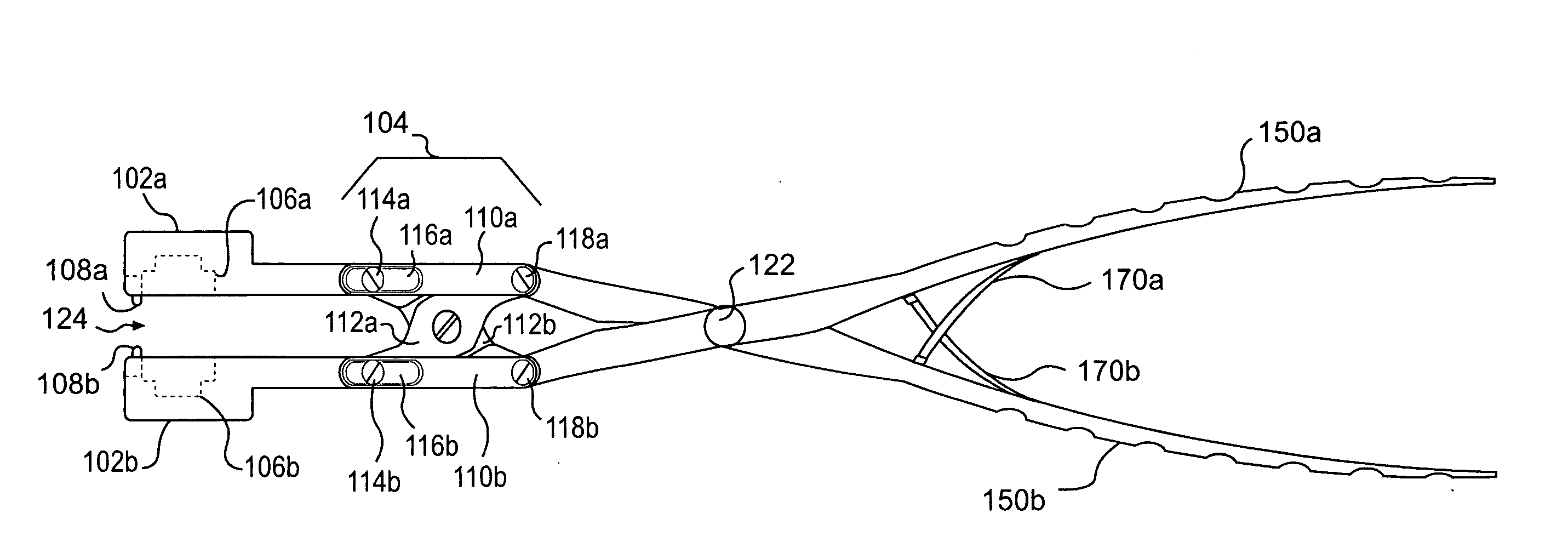
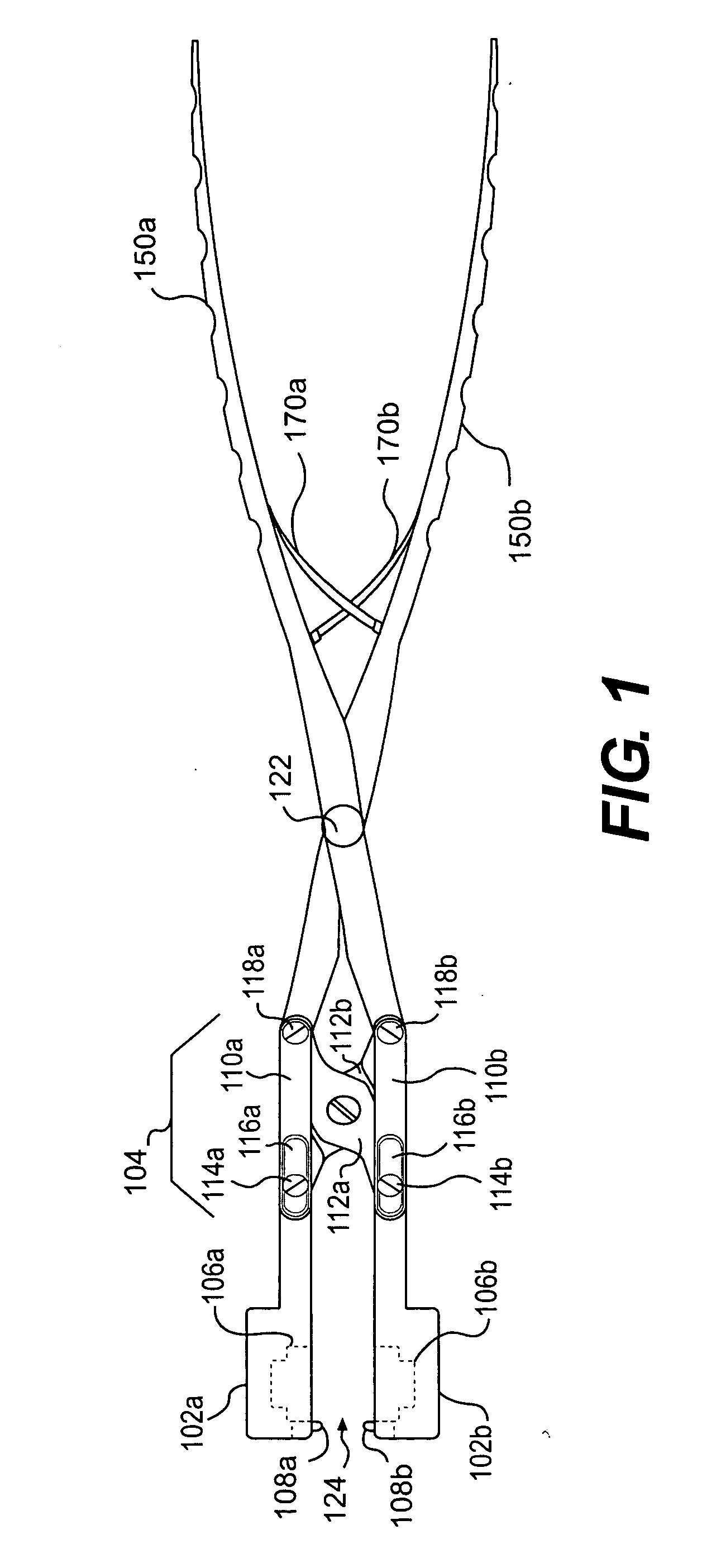
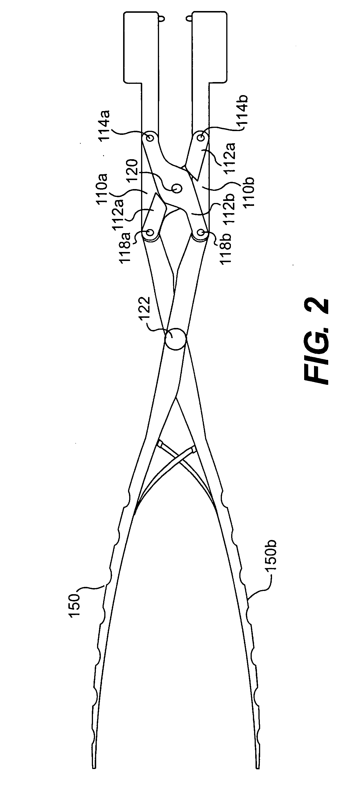
[0012] In one embodiment, the present invention is directed to an apparatus for compressing a shape memory material implant to be implanted in a patient. The apparatus includes opposing dies, an actuator, and a uniformity controller. The opposing dies are configured to grasp the shape memory material implant, when placed therebetween. The actuator actuates the opposing dies toward each other, such that the opposing dies impart forces in substantially direct opposition to each other, against the shape memory material implant, when placed therebetween, so as to compress the shape memory material implant. The uniformity controller provides uniform compression of a given type of shape memory material implant.

Problems solved by technology

A common injury in which such treatment is useful is a ruptured or otherwise damages intervertebral disc.
A common cause of back pain and injury is a rupture or tear in the annulus that allows the nucleus to herniate.
A herniated nucleus can put pressure on neural and ligamentary structures associated with the spine, which can leads to pain in the patient's back and legs.
However, it still can be difficult to keep the cage in the compressed form prior to insertion into a patient.
If the product is shipped to the hospital during warmer summer months, the device will likely encounter temperatures during delivery that exceed the transition temperature.
Thus, it is likely that a surgeon, nurse, or technician would have to compress the cage prior to or during the implantation surgery.
If compressed too much, cracking of the material or “cold working” can occur.
Cold working and cracking of the material can cause the compressed structure to become, at least partially, unrecoverable (“over yielding”), such that the cage does not return to the proper expanded form when heated above the transition temperature.
Above that, risks of cracking and cold working heighten.

Method used


Image

  • Compression device and method for shape memory alloy implants
  • Compression device and method for shape memory alloy implants
  • Compression device and method for shape memory alloy implants

Examples


Embodiment Construction

[0023]FIGS. 1-3 show one embodiment of the present invention embodied in a hand-held compression device 100. Of course, a number of other arrangements are possible while keeping within the scope of the intended scope of the present invention, as defined by the claims provided below. For instance, the compression device need not be hand held, and can work with alternate mechanics as those described below. For instance, the device may be a table-top device. Also, the mechanics may be automatically controlled through electrical components or pneumatics, such that the device is not actuated manually. Thus, the following description should be taken as exemplary.

[0024] As shown in FIG. 1, a compression device 100 is provided. The compression device 100 includes opposing heads 102a and 102b. The opposing heads 102a and 102b include stops 108a and 108b and cavities 106a and 106b. As shown in FIG. 4, in addition to opening towards each other, the cavities 106a and 106b open at distal ends t...


PUM


Abstract

Apparatus and method for compressing a shape memory material implant to be implanted in a patient. The apparatus in some embodiments includes opposing dies, an actuator, and a uniformity controller. The opposing dies are configured to grasp the shape memory material implant, when placed therebetween. The actuator actuates the opposing dies toward each other to compress the shape memory material implant. The uniformity controller of some embodiments provides uniform compression of a given type of shape memory material implant.

Description

FIELD OF THE INVENTION [0001] The present invention generally relates to an apparatus for compressing shape memory implants and a method for compressing and implanting such implants. The apparatus and method are generally intended for use in repairing various defects in bone and tissue, such as ruptured or herniated intervertebral discs. More specifically, the present invention may relate to a method and apparatus for compressing shape memory alloy cages in a controllable and repeatable manner. BACKGROUND OF THE INVENTION [0002] Implants with shape memory features can be efficacious in repairing bone and tissues defects / deficits. The implants can be used to secure, replace, and / or supplement damaged or missing tissue or bone. The shape memory aspect of the implant typically provides added securement by expanding into the space it is to occupy after an implantation. [0003] A common injury in which such treatment is useful is a ruptured or otherwise damages intervertebral disc. An int...

Claims


Application Information

Patent Timeline
Patent Type & Authority Applications(United States)
IPC IPC(8): A61B17/88A61F2/46A61B17/28A61F2/44
CPCA61B17/2812A61F2/4455A61F2/4611A61F2210/0014A61F2002/4475A61F2002/4622A61F2002/4628A61F2002/30092A61F2002/30593
Inventor PETERMAN, MARC M.
Owner WARSAW ORTHOPEDIC INC
Learn More