Distributed network system architecture for collaborative computing

a distributed network and collaborative computing technology, applied in the field of collaborative computing, to achieve the effect of eliminating single point of failure limitation and being convenient to scal

Inactive Publication Date: 2006-11-02
CISCO TECH INC
View PDF3 Cites 87 Cited by
  • Summary
  • Abstract
  • Description
  • Claims
  • Application Information

AI Technical Summary

Benefits of technology

[0010] The system and method of the present invention provide a distributed collaborative computer system that is scalable to handle an arbitrary number of conference participants and eliminates the server as the single point of failure in the system. This is accomplished by providing a plurality of server computers interconnected via one or more high-speed links. Client computers can connect to any available server computer and start or join a conference hosted on either the server computer to which the client computer is connected or any other server in the system. As a result, the system and method of the present invention is easily scalable to support an arbitrary number of participants to a conference by merely adding the appropriate number of server computers to the system. In addition, by replicating the conference information on more than one server computer, the system and method of the present invention eliminate the single point of failure limitation of prior art systems. In fact, if a server hosting or participating in a conference malfunctions, the failure is detected by other server computers and the client computer is able to reconnect to the conference through a new server computer.

Problems solved by technology

In fact, if a server hosting or participating in a conference malfunctions, the failure is detected by other server computers and the client computer is able to reconnect to the conference through a new server computer.

Method used


Image

  • Distributed network system architecture for collaborative computing
  • Distributed network system architecture for collaborative computing
  • Distributed network system architecture for collaborative computing

Examples


Embodiment Construction

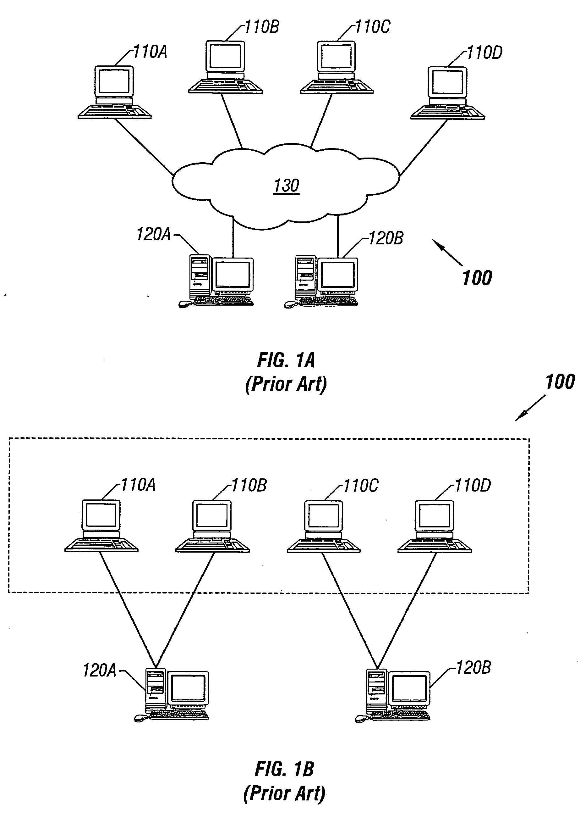
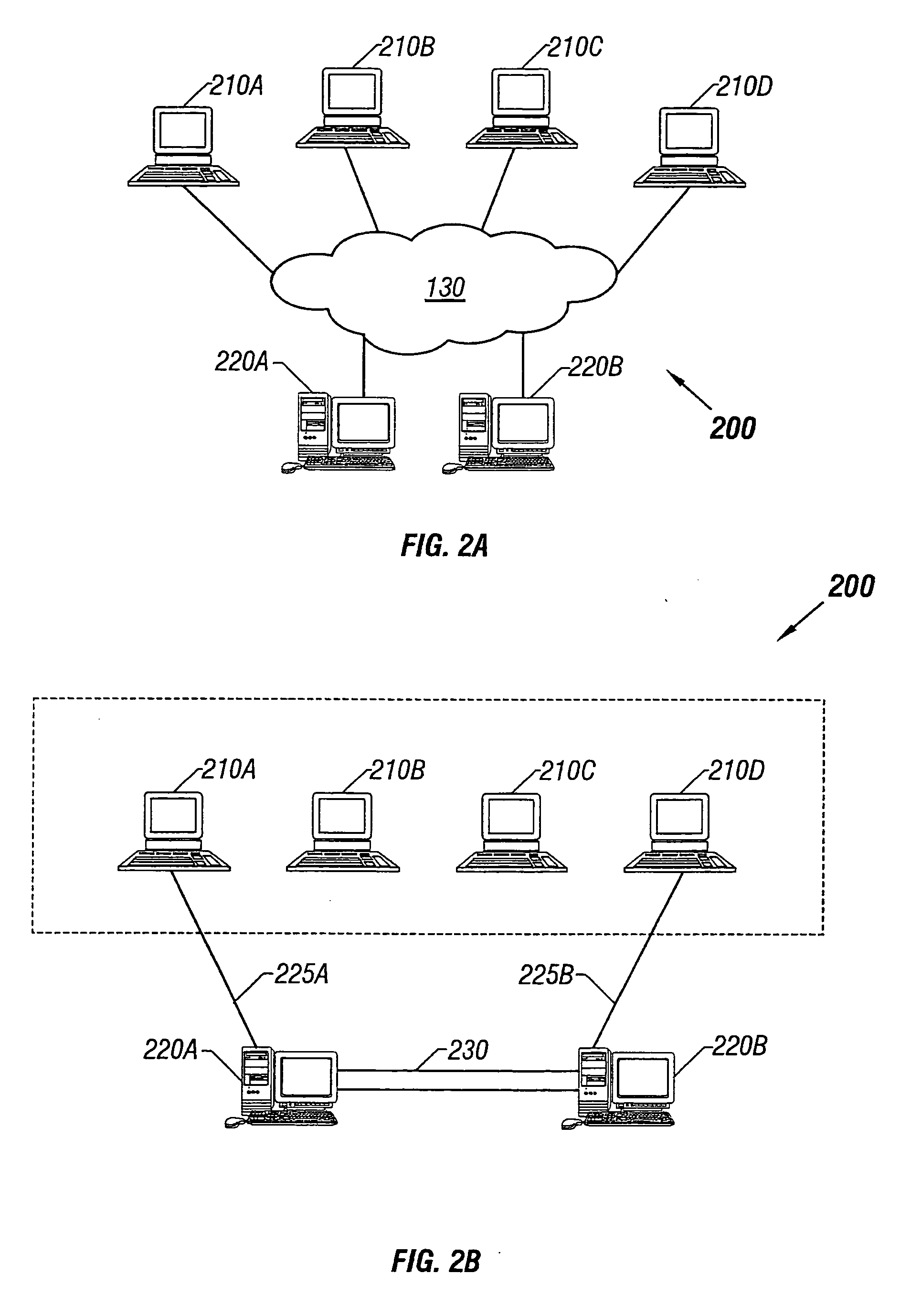
[0030]FIG. 2A illustrates a distributed collaborative computing system 200, in accordance to some embodiments of the invention. Client computers 210n (where n=A, B, C . . . ) are connected to server computers 220n via global-area computer network 130. Unlike in the prior art system of FIGS. 1A and 1B, each client computer 210n can connect to any server computer 220n. Server computers 220n are in turn connected through a high-speed link 230. High speed link 230 allows faster throughput and a higher level of security than global-area network 130. For example, in some embodiments high-speed link 130 is a dedicated T1 or T3 or optical carrier-class link, such as one employing the well-known SONET standard and OC-48 or OC-192 framing. One of ordinary skill in the art will readily recognize that many other equivalent high-speed network standards, including non-optical standards, may be employed to create a high bandwidth link.

[0031]FIG. 2B illustrates the connections established between ...


PUM


Abstract

A distributed collaborative computer system is provided that comprises a plurality of server computers interconnected via a high-speed link. Client computers can connect to any available server computer and start or join a conference hosted on either the server computer to which the client computer is connected or any other server in the system. As a result, the system and method of the present invention is easily scalable to support an arbitrary number of participants to a conference by merely adding the appropriate number of server computers to the system. In addition, by replicating the conference information on more than one server computer, the single point of failure limitation is eliminated. In fact, if a server hosting or participating in a conference malfunctions, the failure is detected by other server computers and the client computer is able to reconnect to the conference through a new server computer.

Description

RELATE BACK INFORMATION [0001] This application is a continuation of application Ser. No. 09 / 751,424 which was filed on Dec. 29, 2000, all of which are expressly incorporated herein by reference.CROSS-REFERENCE TO CD-ROM APPENDIX [0002] An Appendix containing a computer program listing is submitted on a compact disk, which is herein incorporated by reference in its entirety. The total number of compact discs including duplicates is two. Appendix A, which is part of the present specification, contains a list of the files contained on the compact disk. These listings contain material which is subject to copyright protection. The copyright owner has no objection to the facsimile reproduction by anyone of the patent document or the patent disclosure, as it appears in the patent and trademark office patent file or records, but otherwise reserves all copyright rights whatsoever. BACKGROUND OF THE INVENTION [0003] 1. Field of the Invention [0004] The present invention relates generally to ...

Claims


Application Information

Patent Timeline
Patent Type & Authority Applications(United States)
IPC IPC(8): G06F15/16H04L12/18H04L69/40
CPCH04L12/1827H04L69/329H04L69/40H04L67/1095
Inventor ZHU, MINSHEN, JIANLI, STEVENYANG, GUANGHONGZHAO, BINYAN, SHIYUAN, ZHENG
Owner CISCO TECH INC
Why Eureka
Try Eureka