Automatic cleaning device

a cleaning device and automatic technology, applied in the direction of carpet cleaners, electric equipment installation, applications, etc., can solve the problems of unintentional separation of dirt receptacles from the installation chamber, no function of sensing, and contamination of the room, so as to increase the air tightness of the connecting region, simplify the structure, and increase the coupling strength

Inactive Publication Date: 2006-11-09
LG ELECTRONICS INC
View PDF4 Cites 20 Cited by
  • Summary
  • Abstract
  • Description
  • Claims
  • Application Information

AI Technical Summary

Benefits of technology

[0012] It is another object of the present invention to provide an automatic cleaning device having a dirt receptacle sensor unit which can sense the presence of a dirt receptacle with a simplified structure, allow the dirt receptacle to be coupled to a body of the device with an increased coupling strength by the use of a magnetic force, and achieve an increase in the air-tightness of the connecting region between the dirt receptacle and the dirt receptacle sensor unit.
[0013] It is yet another object of the present invention to provide an automatic cleaning device having a dirt receptacle sensor unit, which is capable of allowing a user to easily recognize the presence of a dirt receptacle.

Problems solved by technology

However, the above-described prior art has a problem in that it has no function of sensing the presence of the dirt receptacle.
When a user forgets to put the dirt receptacle into the installation chamber of the body after emptying the dirt receptacle, or the dirt receptacle is unintentionally separated from the installation chamber due to external factors, such as shock, the conventional automatic cleaning device may continue cleaning without knowing the absence of the dirt receptacle.
This causes the suctioned dust and dirt to be directly discharged into the room without passing through the filter of the dirt receptacle, resulting in room contamination.
Furthermore, the dust and dirt may be suctioned into other elements of the device, causing the automatic cleaning device to breakdown.

Method used


Image

  • Automatic cleaning device
  • Automatic cleaning device
  • Automatic cleaning device

Examples


first embodiment

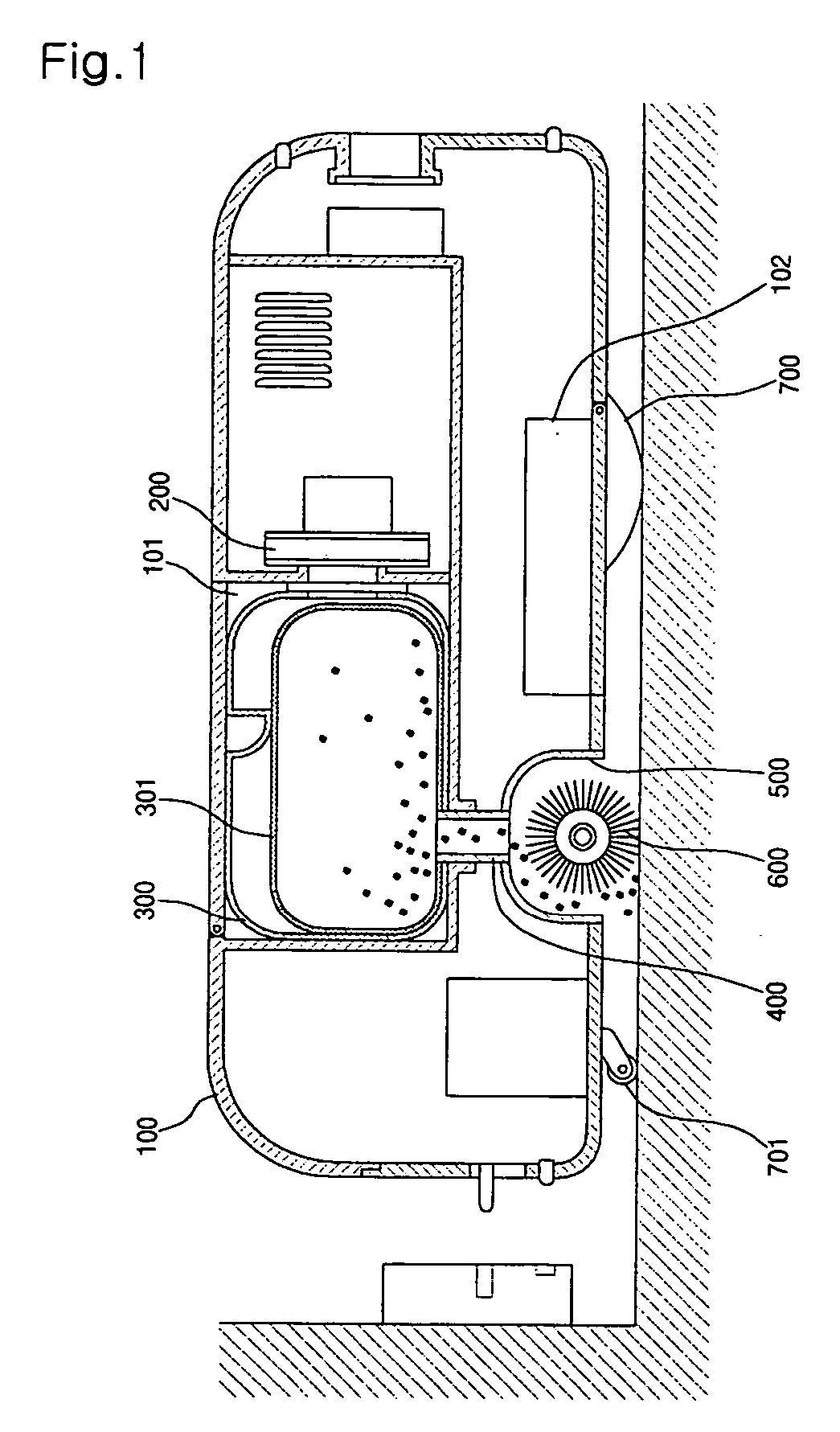
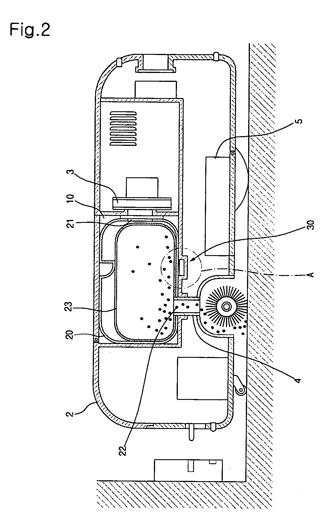
[0050]FIG. 2 is a schematic longitudinal sectional view illustrating an automatic cleaning device in accordance with the present invention. FIG. 3 is an enlarged sectional view of circle A of FIG. 2. FIG. 4 is an enlarged section view illustrating separation of a dirt receptacle of FIG. 3.

[0051] As shown in FIGS. 2 to 4, the automatic cleaning device according to the first embodiment of the present invention comprises: a body 2; a fan motor 3 to generate a suction force; an installation chamber 10 defined in the body 2; a dirt receptacle 20 detachably mounted in the installation chamber 10; and a dirt receptacle sensor unit 30 to sense the presence of the dirt receptacle 20.

[0052] The installation chamber 10 is defined in the body 2 at a position connected with the fan motor 3. Thus, the dirt receptacle 20, which is mounted in the installation chamber 10, is connected with the fan motor 3.

[0053] The dirt receptacle 20 has a through-hole 21, so that the dirt receptacle 20 is connec...

second embodiment

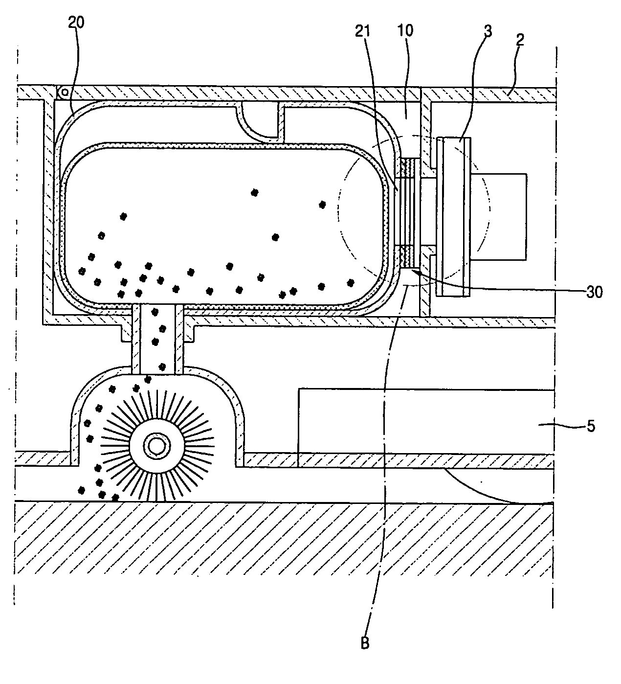
[0061]FIG. 5 is a schematic longitudinal sectional view illustrating an automatic cleaning device in accordance with the present invention. FIG. 6 is an enlarged sectional view of circle B of FIG. 5. FIG. 7 is an enlarged section view illustrating separation of a dirt receptacle of FIG. 6.

[0062] As shown in FIGS. 5 to 7, the automatic cleaning device according to the second embodiment of the present invention comprises: the body 2; the fan motor 3; the installation chamber 10 defined in the body 2 to be connected with the fan motor 3; the dirt receptacle 20 detachably mounted in the installation chamber 10; and the dirt receptacle sensor unit 30 to sense the presence of the dirt receptacle 20.

[0063] The dirt receptacle sensor unit 30 is mounted in the installation chamber 10 so that it senses the absence of the dirt receptacle 20 inside the installation chamber 10 and inputs the sensed result into the controller 5. The dirt receptacle sensor unit 30 of the present embodiment includ...

third embodiment

[0068]FIG. 8 is a schematic longitudinal sectional view illustrating an automatic cleaning device in accordance with the present invention. FIG. 9 is an enlarged sectional view of circle C of FIG. 8. FIG. 10 is an enlarged section view illustrating separation of a dirt receptacle of FIG. 9.

[0069] As shown in FIGS. 8 to 10, the automatic cleaning device according to the third embodiment of the present invention comprises: the body 2; the fan motor 3; the installation chamber 10 defined in the body 2 to be connected with the fan motor 3; the dirt receptacle 20 detachably mounted in the installation chamber 10; and the dirt receptacle sensor unit 30 to sense the presence of the dirt receptacle 20.

[0070] The dirt receptacle sensor unit 30 is mounted in the installation chamber 10 so that it senses the absence of the dirt receptacle 20 inside the installation chamber 10 and inputs the sensed result into the controller 5. The dirt receptacle sensor unit 30 of the present embodiment inclu...


PUM


Abstract

Disclosed herein is an automatic cleaning device having a dirt receptacle sensor unit to sense the presence of a dirt receptacle. The dirt receptacle is detachably mounted in an installation chamber defined in a body of the automatic cleaning device.

Description

BACKGROUND OF THE INVENTION [0001] 1. Field of the Invention [0002] The present invention relates to an automatic cleaning device, and, more particularly, to an automatic cleaning device having a dirt receptacle sensor unit to sense the presence of a dirt receptacle. [0003] 2. Description of the Related Art [0004] Generally, an automatic cleaning device is a self-running vacuum cleaner. The automatic cleaning device automatically finds its way back to its charging station to recharge when needed. If the cleaning hasn't been completed when the automatic cleaning device needs to be charged, the automatic cleaning device continues cleaning when charging is finished. [0005]FIG. 1 is a schematic longitudinal sectional view illustrating the general configuration of a conventional automatic cleaning device. [0006] As shown in FIG. 1, the conventional automatic cleaning device comprises: a body 100; a fan motor 200 mounted in the body 100 to generate a suction force; and a dirt receptacle 3...

Claims


Application Information

Patent Timeline
Patent Type & Authority Applications(United States)
IPC IPC(8): E01H1/08
CPCA47L9/1436A47L2201/00A47L9/1472A47L9/28A47L11/00
Inventor BAEK, OH-HYUN
Owner LG ELECTRONICS INC
Why Eureka
Try Eureka