Devices, systems and methods for controlling introduction of additives into an internal combustion engine

a technology of additives and internal combustion engines, applied in the field of internal combustion engines, can solve the problems of limiting the contaminating exhaust emissions, the “chemically correct” mixture of fuel and air not always getting the best, and the loss of economy

Inactive Publication Date: 2006-11-09
S I S POWER
View PDF28 Cites 18 Cited by
  • Summary
  • Abstract
  • Description
  • Claims
  • Application Information

AI Technical Summary

Benefits of technology

[0030]FIG. 11 illustrates an injection control system according to an additional embodiment of the invention.
[0031]FIG. 12 shows a flow chart depicting th...

Problems solved by technology

For various reasons, a “chemically correct” mixture of fuel and air does not always get the best results by way of limiting contaminating exhaust emissions.
Unfortunately, most of the steps that can be taken to reduce the amounts of CO and HC also tend to increase the NOX emission, with some loss in economy.
This minimizes the amount of CO and HC developed, but it also incr...

Method used


Image

  • Devices, systems and methods for controlling introduction of additives into an internal combustion engine
  • Devices, systems and methods for controlling introduction of additives into an internal combustion engine
  • Devices, systems and methods for controlling introduction of additives into an internal combustion engine

Examples


Embodiment Construction

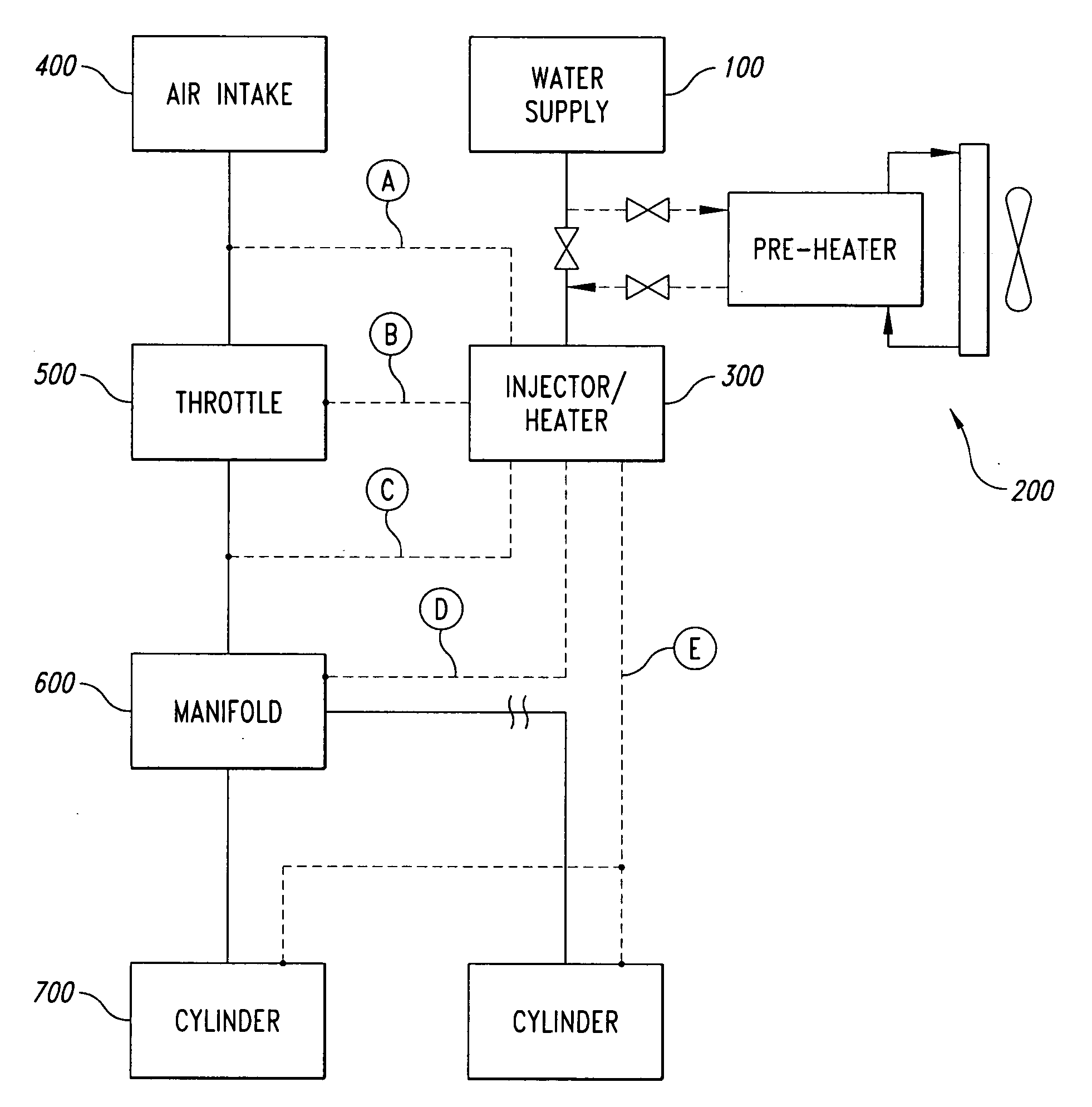
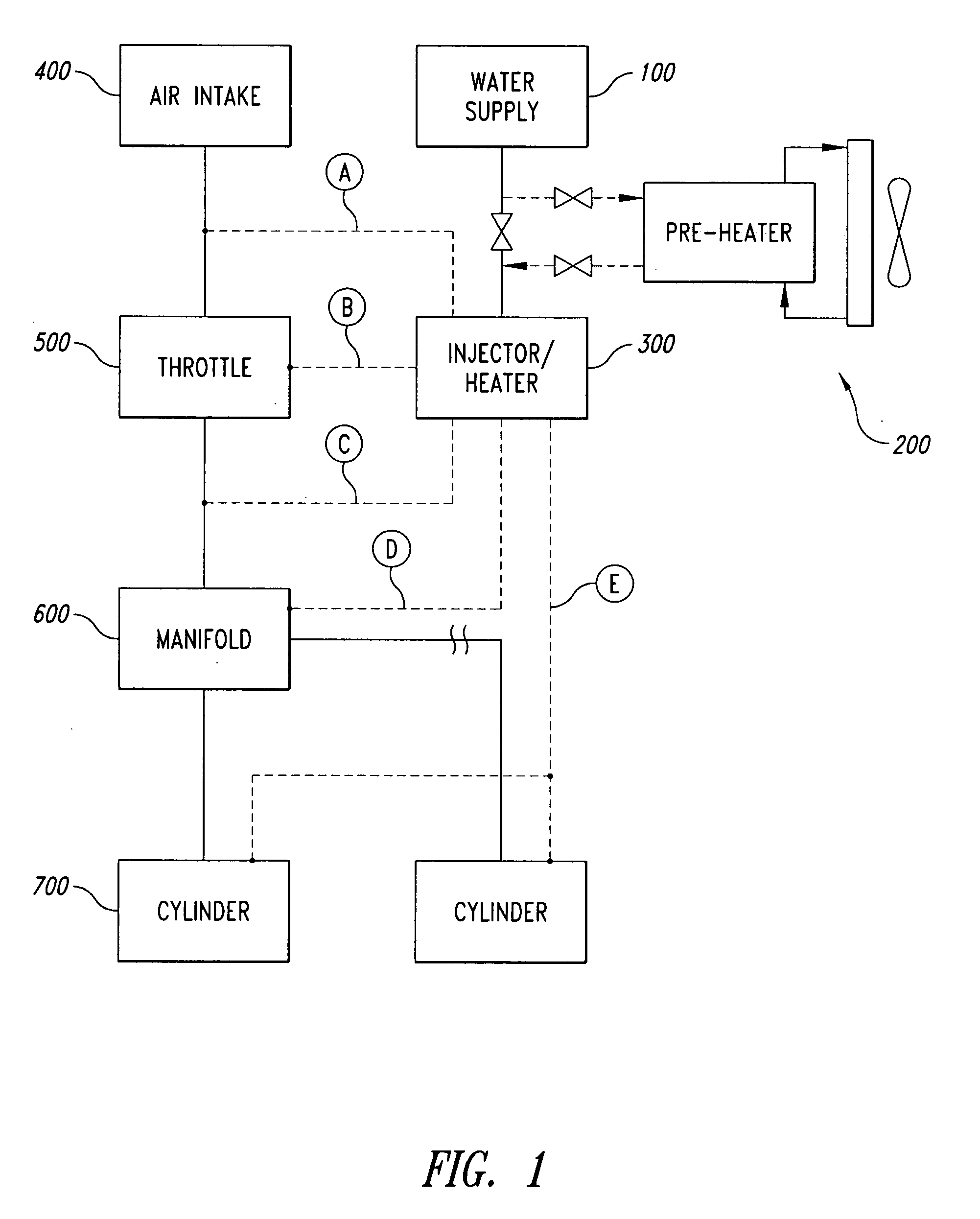
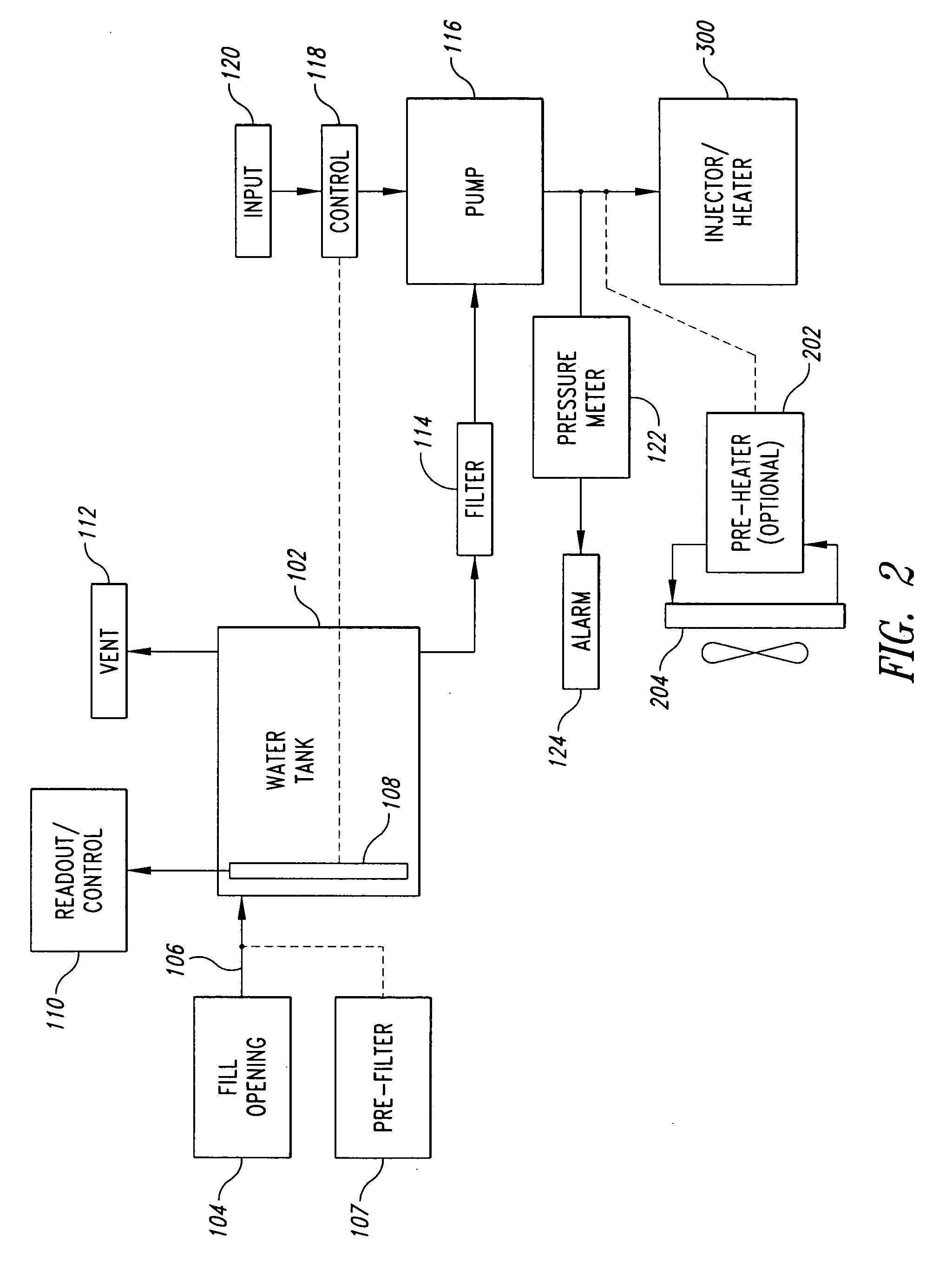
[0033] The present detailed description is directed toward devices, systems and methods for controlling the introduction of water into the combustion chamber of an internal combustion engine. Many specific details are provided and illustrated to help explain the construction and operation of the particular embodiments of the invention. The invention could take on other embodiments, and one of ordinary skill in the art, having reviewed the present disclosure and corresponding drawings in their entireties, would readily appreciate modifications that could be made to the illustrated embodiments without deviating from the spirit of the invention. Thus the invention is not to be limited to the specific embodiments illustrated in the drawings and described in connection therewith.

[0034]FIGS. 1-8 and the accompanying descriptive text collectively illustrate only some of the various systems for introducing water into the air-fuel mixture burned in the combustion chamber of an internal comb...


PUM


Abstract

A water injection control system includes a control unit adapted to receive one or more of a plurality of sensor signals from sensors provided as standard equipment in a vehicle, and to provide one or more control signals configured to control the operation of a water injection system associated with an engine of the vehicle. The received sensor signals may include signals from sensors such as an O2 sensor, an engine coolant temperature sensor, a mass air flow sensor, a manifold absolute pressure sensor, a crankshaft position sensor, a vehicle speed sensor, an intake air temperature sensor, and a throttle position sensor. The control signals provided by the controller may include signals for controlling functions such as water injector pulse rate and pulse width, water pump operation, water heater power, dashboard indicators, and PCU O2 sensor input.

Description

BACKGROUND OF THE INVENTION [0001] 1. Field of the Invention [0002] This invention relates to internal combustion engines, and in particular, to devices, systems and methods for introducing water into the combustion chamber prior to or during ignition. [0003] 2. Description of the Related Art [0004] The subject system utilizes a combination of well documented principles of operation. With respect to the combustion process in internal combustion engines, certain remarks will be made herebelow about the way a hydrocarbon fuel burns in an internal combustion engine, as well as the effect the fuel / air ratio has on the three main atmospheric contaminants discharged by such engine. These are limited by federal law and include CO (Carbon Monoxide), HC (unburnt hydrocarbons) and NOX (oxides of nitrogen). [0005] For various reasons, a “chemically correct” mixture of fuel and air does not always get the best results by way of limiting contaminating exhaust emissions. Thus, ideally, for maximu...

Claims


Application Information

Patent Timeline
IPC IPC(8): F02M25/025
CPCF02B47/02F02M25/03Y02T10/121F02M25/028F02M25/0227F02M25/035F02M25/0225Y02T10/12
Inventor MORGAN, GLEN A.OVERLY, EUGENEWOOD, THOMAS M.ROWBERRY, WAYNEISEMONGER, DEAN
Owner S I S POWER
Why Eureka
Try Eureka