Grooved-surface air conduit for injection molds

Active Publication Date: 2006-11-09
TOP GRADE MOLDS
View PDF2 Cites 6 Cited by
  • Summary
  • Abstract
  • Description
  • Claims
  • Application Information

AI Technical Summary

Benefits of technology

[0020] The invention provides a mold having similar functionality to molds of the prior art but which requires less machining to produce and which can be more robust. Other advantages, features and characteristics of the present invention, as well as methods of operation and functions of t

Problems solved by technology

While this drilling technique provides adequate functionality, it can be costly and time consuming.
For example, provision of the air circuits in the prior art mold illustrated may require up to 80 hours of drilling time.
This drilling technique can also tend to weaken the structure of the mold, as the mold can already be crowded with numerous other drilled bores.

Method used


Image

  • Grooved-surface air conduit for injection molds
  • Grooved-surface air conduit for injection molds
  • Grooved-surface air conduit for injection molds

Examples


Embodiment Construction

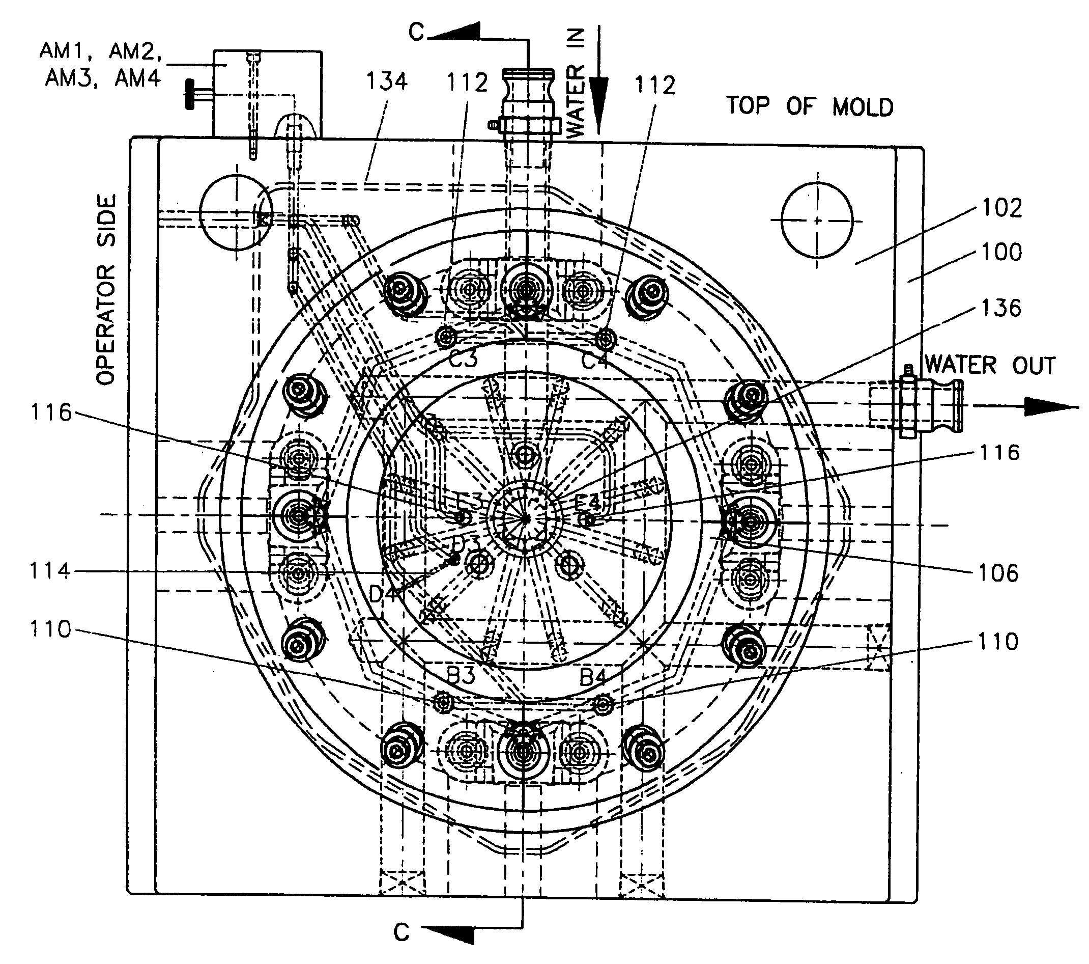
[0028] A preferred embodiment of the present invention will now be described with reference to FIGS. 5, 6 and 7, which show a single-cavity container mold assembly that uses mechanical knockout systems for collet motion. This mold assembly, as shown in FIG. 6, comprises a number of mold parts including a core plate 100, a core block 102, a cavity block 104, a set of collets 106, and a core cap 108. The core plate 100, core block 102 and core cap 108 collectively define a core portion or die of the mold. The cavity block 104 and collets 106 collectively define a cavity portion or die of the mold. The various parts have abutment surfaces 200 and further have an operative configuration wherein the parts are pressed against one another so as to define a mold having an interior mold cavity, as shown in FIG. 6, for receiving hardenable synthetic resin. After resin has been injected into the cavity and allowed to harden to form a molded article, the core portion and the cavity portion can ...


PUM


Abstract

An improved mold assembly for producing an article and for use with an air source is disclosed. The mold assembly is of the type including at least two mold portions configurable to form a mold having an interior mold cavity in the shape of said article, one or more of said mold portions each including an interior conduit for delivering air from said air source in use. The improvement comprises, for each of said one or more mold portions, a pair of mold parts each having an abutment surface, one of said abutment surfaces having defined therein a groove. The pair of mold parts is disposed in an operative configuration whereat they define at least in part said each mold portion, whereat the abutment surfaces lie flush against one another and whereat the groove defines at least part of the interior conduit in said each mold portion.

Description

FIELD OF THE INVENTION [0001] This invention relates to injection molds and, in particular, to injection molds including interior conduits for directing air from an air source external to the injection mold to locations inside the injection mold. This application claims benefit of the filing date of and right of priority of U.S. Provisional Patent Application Ser. No. 60 / 679,112 filed May 9, 2005 under 35 USC § 119(e). BACKGROUND OF THE INVENTION [0002] Injection molds often use air to achieve motion of various components. An exemplary single-cavity container mold of the prior art and of this general type is illustrated in FIG. 1 through FIG. 4. This mold includes a core plate, a core block, a core cap, a cavity block, a cavity insert and a set of collets. In use as shown in FIG. 4, the core block, core cap, cavity block, cavity insert and collets define a void shaped in the form of a pail, for receipt of hardenable resin. After resin has been injected into the void and allowed to h...

Claims


Application Information

Patent Timeline
IPC IPC(8): B29D11/00
CPCB29C33/046B29C33/301B29C45/7312B29C2945/76732B29C2045/7318B29C2045/822B29C2945/76498B29C45/82
Inventor CICCONE, VINCEKNEZOVIC, JERKOWONG, ALBERT
Owner TOP GRADE MOLDS
Why Eureka
Try Eureka