Abradable and/or abrasive coating and brush seal configuration

a technology of abrasive coating and brush seal, which is applied in the direction of engine seals, leakage prevention, machines/engines, etc., can solve the problems of rotor damage, limited application of brush seals in such regions, and the material available for backing plates,

Inactive Publication Date: 2006-11-09
GENERAL ELECTRIC CO
View PDF16 Cites 21 Cited by
  • Summary
  • Abstract
  • Description
  • Claims
  • Application Information

AI Technical Summary

Problems solved by technology

However, the application of brush seals to such regions is limited by the backing-plate bending stress and bristle-bending stress capabilities of the brush seal assembly.
One of the limitations precluding the use of brush seals in applications having higher temperatures and higher pressure drops

Method used


Image

  • Abradable and/or abrasive coating and brush seal configuration
  • Abradable and/or abrasive coating and brush seal configuration
  • Abradable and/or abrasive coating and brush seal configuration

Examples


Embodiment Construction

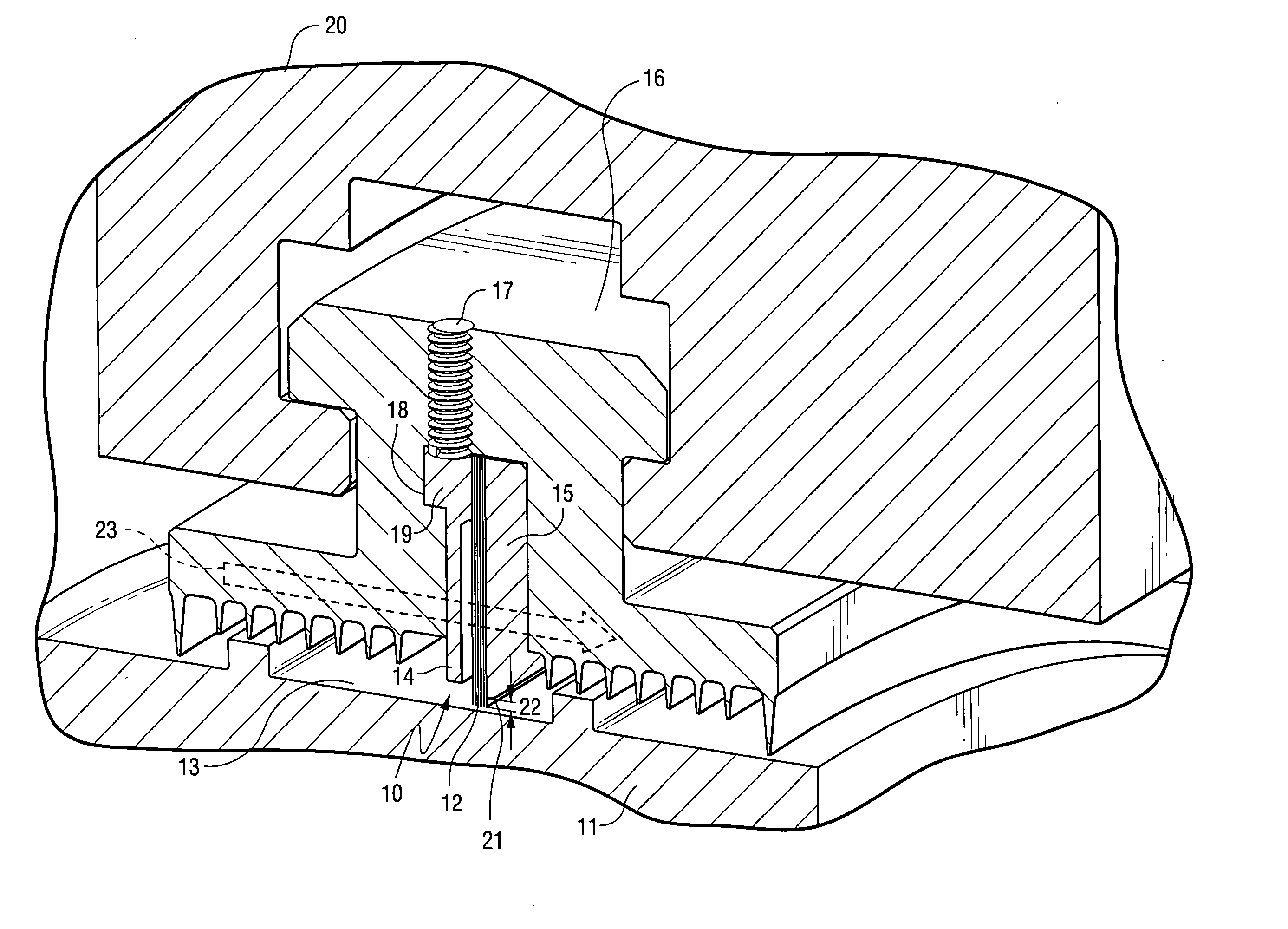
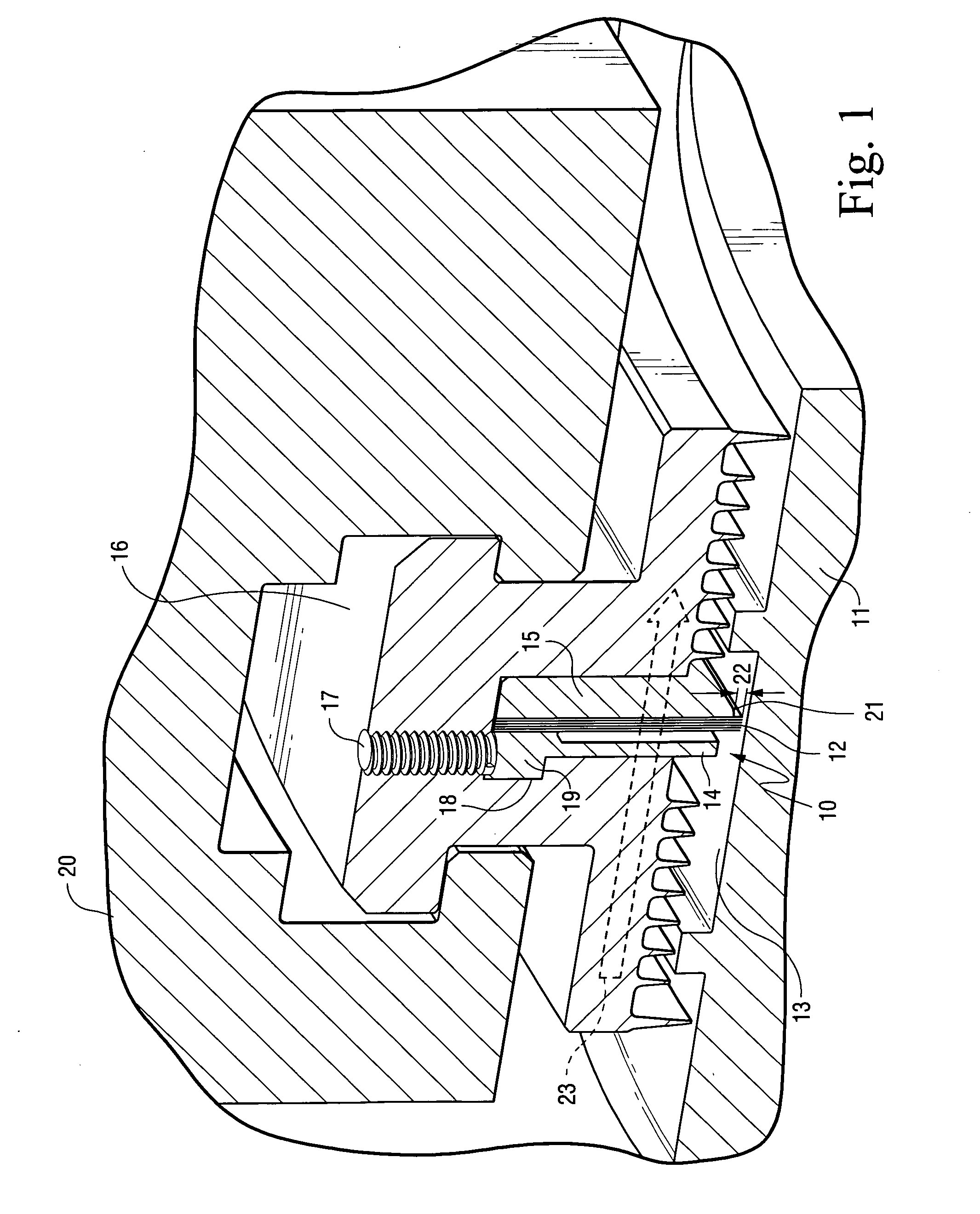
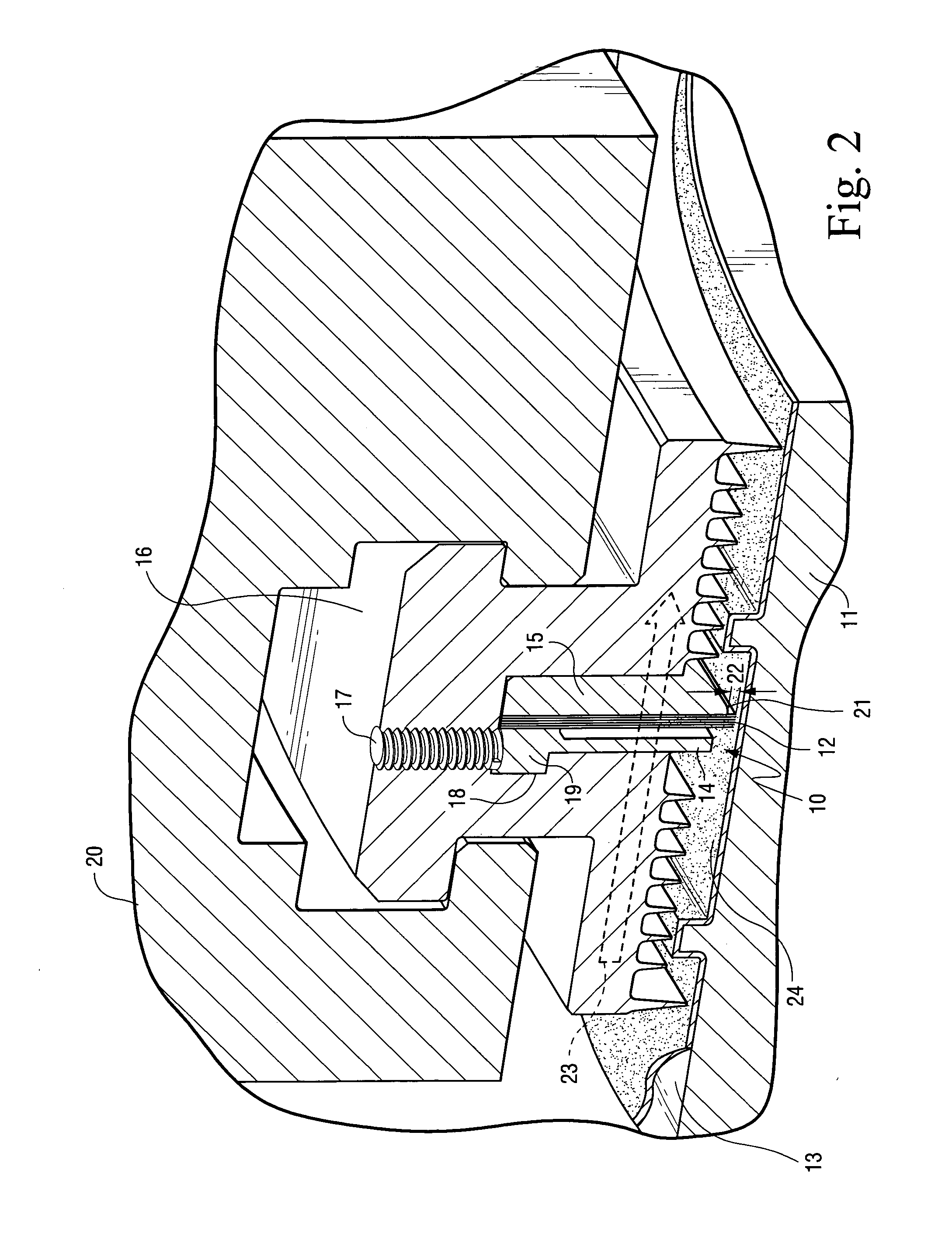
[0007]FIG. 1 is a cross-sectional, perspective view showing a brush holder assembly 10 engaging a rotor 11 of a turbine (not shown). The brush holder assembly 10 includes a plurality of wire bristles 12 engaging a surface 13 of rotor 11. Bristles 12 are positioned between a front plate 14 and a backing plate 15, which provides support for bristles 12. Bristles 12, front plate 14, and backing plate 15, which comprise brush holder assembly 10, are welded together on top. They are mounted within a packing ring 16, and held within ring 16 by a set screw 17 which urges a shoulder 18 of front plate 14 against an indentation 19 in packing ring 16 designed to accommodate shoulder 18. Packing ring 16 is, in turn, supported by a packing holder 20 mounted within the turbine.

[0008] Brush holder assembly 10 is urged against surface 13 of rotor 11 by a spring assembly (not shown) exerting a positive force against assembly 10 in the direction of rotor 11. The distance between surface 13 of rotor ...


PUM


Abstract

An abradable coating and/or an abrasive coating applied to the rotor of a steam or gas turbine allows the temperature and pressure drop capabilities of conventional brush seal assemblies to be increased. The pressure drop capability of brush seals is closely related to fence height, i.e., the distance between the rotor and the bottom edge of the backing plate supporting the brush seal wire bristles. Application of the abradable or abrasive coating allows the fence height to be reduced and the pressure capability of a brush seal assembly increased commensurately because the risk of the backing plate rubbing against the surface of the rotor, so as to cause damage to the rotor, is reduced. In addition, the backing plate can be made from a higher strength material that can withstand higher temperatures because any contact between the backing plate and the rotor results in no damage to the rotor, but rather a gradual reduction of the backing plate as it wears.

Description

BACKGROUND OF THE INVENTION [0001] The present invention relates to turbines, and more particularly, to the use of an abradable coating and / or an abrasive coating with turbine brush seals to increase their pressure drop and temperature capabilities. [0002] Turbine brush seals are contacting seals which typically include a highly flexible seal pack that consists of thousands of wire bristles that continuously adapt to the moving surface of a turbine rotor. Typically, the wire bristles are made from a collection of very fine metal bristles that form a curtain to produce a seal, yet are sufficiently compliant to withstand movement of the rotor. Typically, the bristles have low wear rates. [0003] Currently, brush seals are applied to high pressure (HP), intermediate pressure (IP), low pressure (LP) and end packing regions of single-flow and opposed-flow combined rotors. However, the application of brush seals to such regions is limited by the backing-plate bending stress and bristle-ben...

Claims


Application Information

Patent Timeline
IPC IPC(8): F16J15/44
CPCF16J15/3288F16J15/445F16J15/442
Inventor KOWALCZYK, MARK W.COUTURE, BERNARD A.RIVAS, FLOR D.C.
Owner GENERAL ELECTRIC CO
Why Eureka
Try Eureka