
Crash box

a box and screw technology, applied in the field of crash boxes, can solve the problems of ineffective non-rotatable connection between the respective rotary catch and the screw bolt, and the inability to rotate the tolerance compensating bolt, etc., and achieve the effects of reducing the overall weight of the crash box, reducing the number of screw elements, and facilitating assembly

Inactive Publication Date: 2006-11-09
BENTELER AUTOMOBILTECHNIK GMBH
View PDF9 Cites 29 Cited by
  • Summary
  • Abstract
  • Description
  • Claims
  • Application Information

AI Technical Summary

Benefits of technology

[0011] According to another feature of the present invention, the rotary catch may be realized by providing protrusions in the form of lugs or lobes on the inside circumference of the tolerance compensating bolt which lock onto the screw bolt. A screw bolt with right-hand thread would come into contact with the rotary catch when the first one of the tolerance compensating bolts, which has a thread opposite to the screw bolt, i.e. left-hand thread, is inserted. As the screw bolt is turned clockwise, this tolerance compensating bolt gets unscrewed from the left-hand thread of the spacer sleeve and thereby moves into abutment against the inner side of the longitudinal member. As rotation of the screw bolt is continued and the non-rotatable connection between the respective rotary catch and the screw bolt becomes no longer effective because the rotary catch breaks or disintegrates, the screw bolt moves further into the spacer sleeve until the head-distal end of the screw bolt comes into contact with the second one of the tolerance compensating bolts and its rotary catch. As a consequence of the opposite thread, i.e. right-hand thread, of the second tolerance compensating bolt in relation to the first tolerance compensating bolt, the second tolerance compensating bolt gets unscrewed from the spacer sleeve and comes into contact with the opposite inner side of the longitudinal member. Continued rotation of the screw bolt also destroys the rotary catch of the second tolerance compensating bolt to such an extent that further rotation of the tolerance compensating bolts is no longer possible. In this way, opposite sides of the longitudinal member mutually support one another and existing assembly tolerances are compensated.
[0013] According to another feature of the present invention, the rotary catch may be formed as a plastic ring, e.g. of polyamide, for blocking the thread turns of the screw bolt in relation to the tolerance compensating bolts at least along a partial portion of the circumference. The anti-rotation mechanism may be implemented by different types of inserts or geometric variations, such as, e.g., shearing pins which release the clamping action between the tolerance compensating bolts and the screw bolt, when a maximum load has been exceeded, so that the screw bolt can be turned further in relation to the immobile tolerance compensating bolt. A further benefit is also that the plastic rotary catch may subsequently secure the screw bolt place so as to prevent inadvertent loosening of the screw bolt.
[0014] A crash box according to the present invention is easy to assemble, without requiring the presence of wide stop plates with need room for a tool. By eliminating the need for wide stop plates, the overall weight of the crash box is also reduced. Installation of the crash box is not accompanied by a deformation of crash box components or components of the longitudinal member. Tolerance compensation is realized exclusively by special screw elements and respective oblong holes in the longitudinal members for passage of the screw bolts. The number of screw elements is also reduced. Another benefit relates to the absence of any installation aids for assembly in X-direction, i.e. in longitudinal direction of the vehicle. The X-direction is defined by the insertion depth of the attachment portion which insertion depth in turn is limited by a stop plate bearing upon an end flange of the longitudinal member. It is important to note in this context that the end flange and the stop plate fulfill only the function as stop and do not assist in any way in the actual threaded securement of the crash box to the longitudinal member. As a result, the dimensions of the end flange and the stop plate can be sized very small, which means that the available installation space in the engine compartment is increased. This is advantageous as far as vehicle design is concerned. In general, a screw connection is possible in Y and Z directions, i.e. in a direction transversely to the travel direction and in vertical direction.
[0015] According to another feature of the present invention, the attachment portion and the stop plate may form a single-piece structure. Suitably, the attachment portion may be formed by stamping the stop plate, using a debossing process for example. The attachment portion is significantly smaller in width than the clear width of the longitudinal member for engagement by the attachment portion. The thus created circumferential gap between the attachment portion and the walls of the longitudinal member enables a positioning of the bumper and the attached crash box, without encountering any rubbing between the components during assembly and without experiencing any jamming action. Tolerances of the longitudinal member can be compensated by this gap which may range about 3 mm.

Problems solved by technology

As rotation of the screw bolt is continued and the non-rotatable connection between the respective rotary catch and the screw bolt becomes no longer effective because the rotary catch breaks or disintegrates, the screw bolt moves further into the spacer sleeve until the head-distal end of the screw bolt comes into contact with the second one of the tolerance compensating bolts and its rotary catch.
Continued rotation of the screw bolt also destroys the rotary catch of the second tolerance compensating bolt to such an extent that further rotation of the tolerance compensating bolts is no longer possible.

Method used


Image

  • Crash box
  • Crash box
  • Crash box

Examples


Embodiment Construction

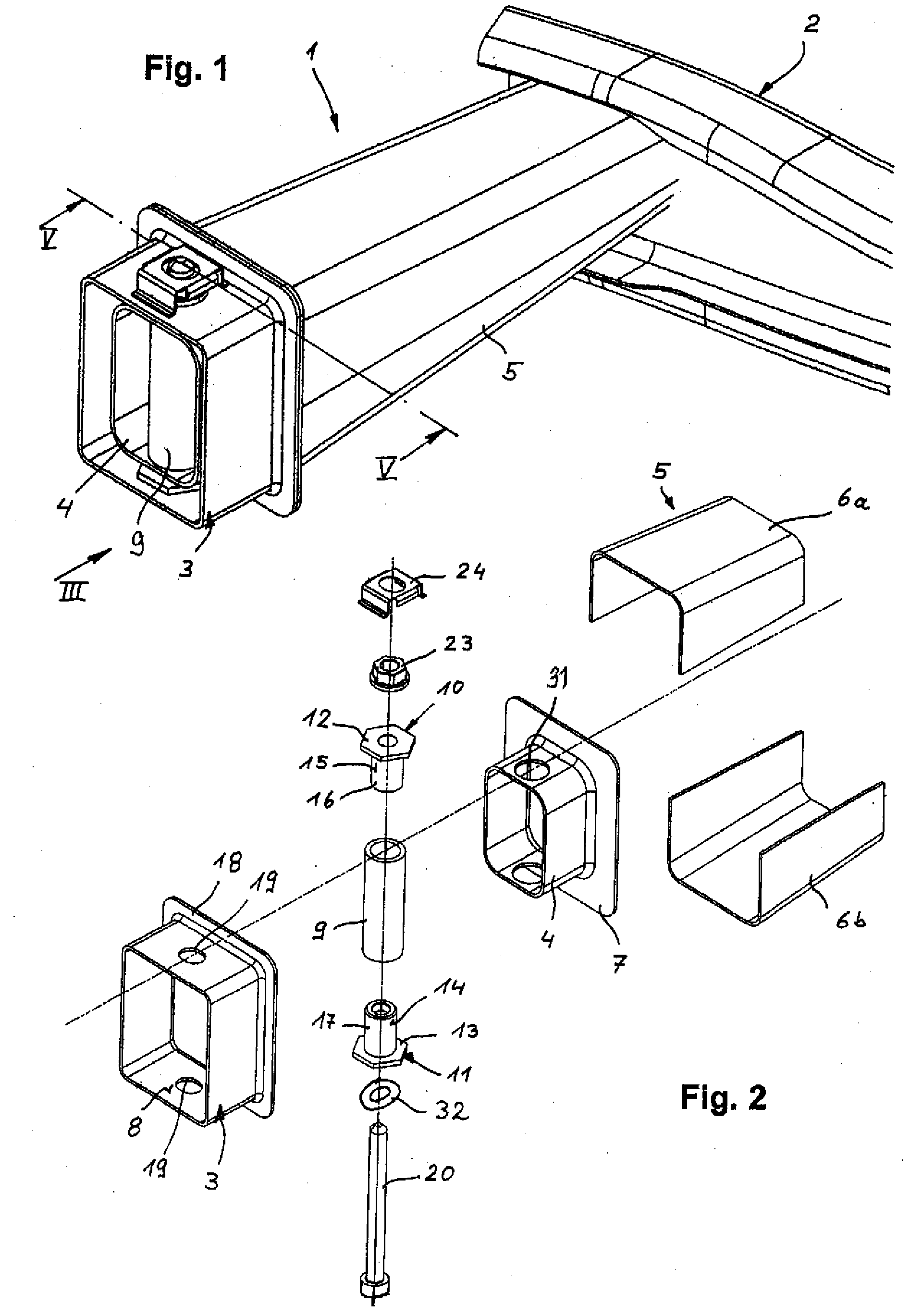
[0026] Throughout all the Figures, same or corresponding elements are generally indicated by same reference numerals. These depicted embodiments are to be understood as illustrative of the invention and not as limiting in any way. It should also be understood that the drawings are not necessarily to scale and that the embodiments are sometimes illustrated by graphic symbols, phantom lines, diagrammatic representations and fragmentary views. In certain instances, details which are not necessary for an understanding of the present invention or which render other details difficult to perceive may have been omitted.

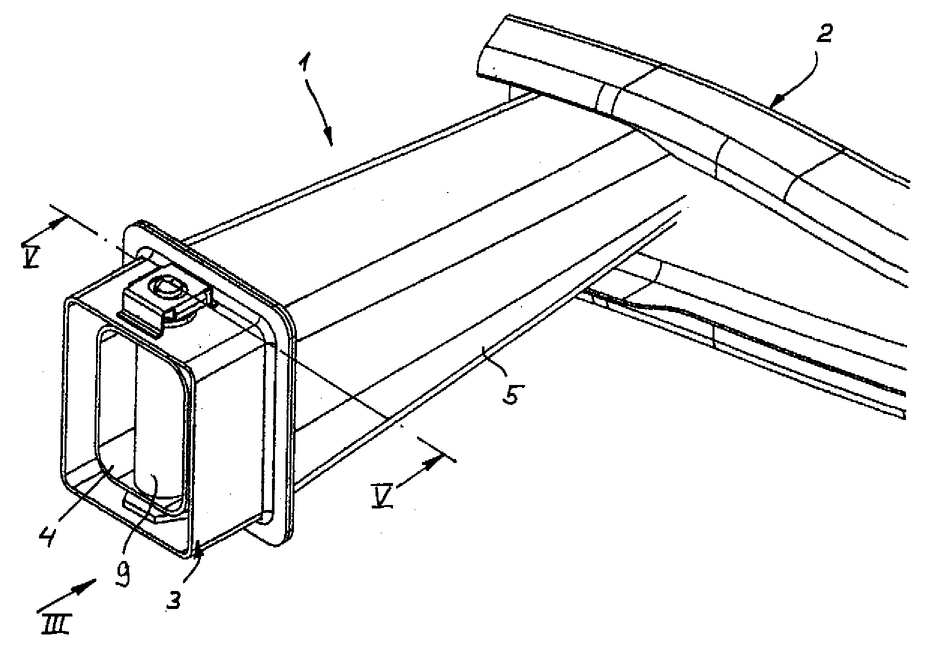
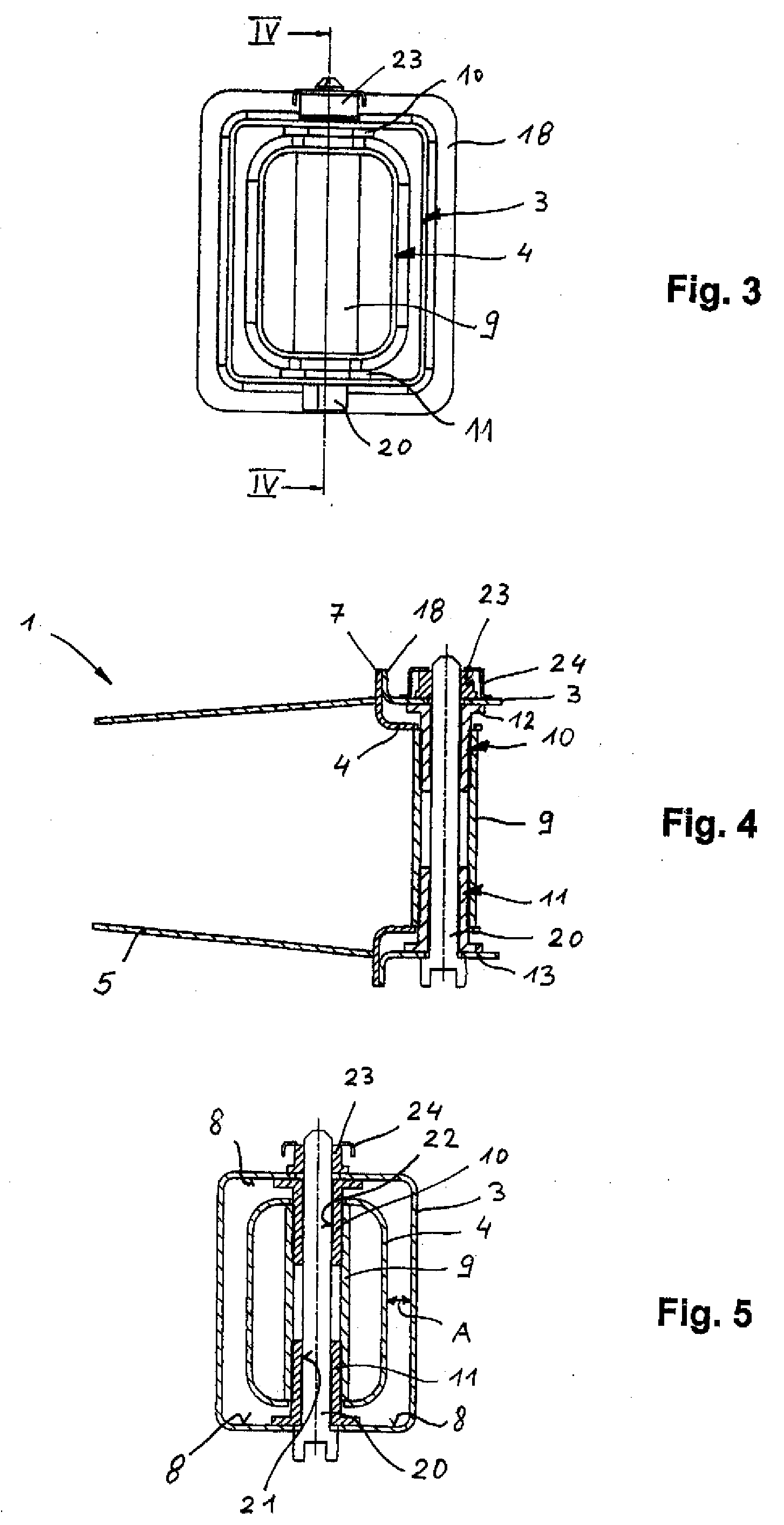
[0027] Turning now to the drawing, and in particular to FIG. 1, there is shown a perspective illustration of one embodiment of a crash box according to the present invention, generally designated by reference numeral 1 and intended for connection to a bumper cross member 2 and a longitudinal member 3 of an unillustrated motor vehicle. The crash box 1 includes two parts, name...


PUM


Abstract

A crash box for a motor vehicle includes an attachment portion which engages a longitudinal member of the motor vehicle and is secured thereto by at least one screw bolt which extends through a spacer sleeve. The spacer sleeve is securely fixed to the attachment portion and has two threaded portions of opposite pitch. Inserted from opposite sides of the spacer sleeve are tolerance compensating bolts, which are each provided with an inner rotary catch for interaction with an outer thread of the screw bolt. When the screw bolt is screwed in, the tolerance compensating bolts are thus moved apart until abutting against opposite inside wall surfaces of the longitudinal member. The screw bolt engages hereby a nut on an outside of the longitudinal member so that the attachment portion is now held without clearance on the longitudinal member by a head portion of the screw bolt and one of the tolerance compensating bolts, and by the other one of the tolerance compensating bolts and the nut.

Description

CROSS-REFERENCES TO RELATED APPLICATIONS [0001] This application claims the priority of German Patent Application, Serial No. 10 2005 021 661.7, filed May 6, 2005, pursuant to 35 U.S.C. 119(a)-(d), the content of which is incorporated herein by reference. BACKGROUND OF THE INVENTION [0002] The present invention relates, in general, to a crash box for a motor vehicle. [0003] Nothing in the following discussion of the state of the art is to be construed as an admission of prior art. [0004] Crash boxes are thin-walled, typically rectangular elements of steel, aluminum, or plastic, and disposed between a bumper cross member and a longitudinal member of a motor vehicle, for preventing damage to the vehicle body in the event of frontal or rear-end collisions at low speed. Crash boxes can be manufactured by joining compressed sheet-metal shells, or in single-piece construction using an extruded aluminum section for example. In the event of an impact, the crash box converts the generated ki...

Claims


Application Information

Patent Timeline
IPC IPC(8): B60R19/34
CPCB60R19/34Y10T403/75B62D21/152
Inventor GONZALEZ, DIEGO CESARSTRAZNIKIEWICZ, DARIUSZ
Owner BENTELER AUTOMOBILTECHNIK GMBH
Learn More