
Liquid crystal display device and manufacturing method therefor

Inactive Publication Date: 2006-11-09
SHARP KK
View PDF24 Cites 13 Cited by
  • Summary
  • Abstract
  • Description
  • Claims
  • Application Information

AI Technical Summary

Benefits of technology

[0015] By this aspect of the present invention, it is possible to realize a liquid crystal display device having good half-tone viewing angle characteristics.
[0018] By this aspect of the present invention, it is possible to manufacture liquid crystal display devices having good half-tone viewing angle characteristics.
[0020] It is possible to realize a liquid crystal display device having good half-tone viewing angle characteristics by the present invention.

Problems solved by technology

However, this TN mode has a problem of low viewing angle characteristics.
However, there are some big problems to be solved also in the MVA mode liquid crystal display devices.

Method used


Image

  • Liquid crystal display device and manufacturing method therefor
  • Liquid crystal display device and manufacturing method therefor
  • Liquid crystal display device and manufacturing method therefor

Examples


example 1

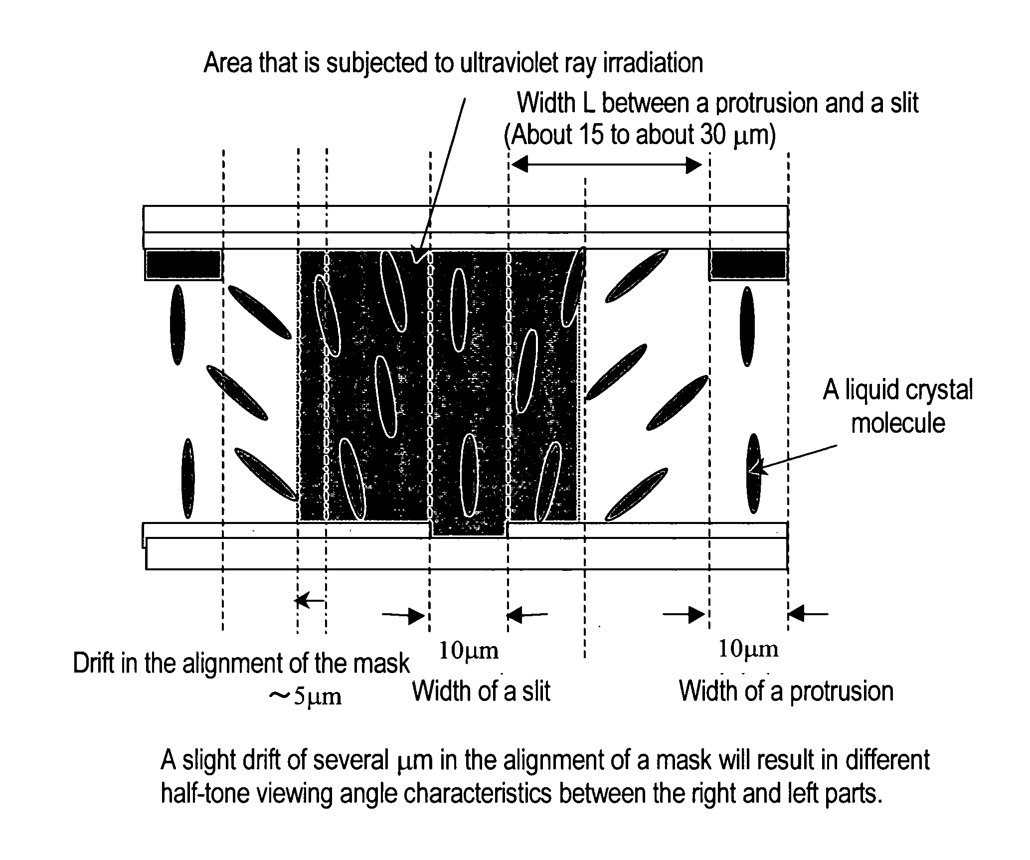
[0098] A bifunctional photopolymerizable compound having a ring structure was dissolved in an amount of 2.0 wt. % in a negative type liquid crystal having a refractive index anisotropy of 0.08, and a photoreaction initiator was added in an amount of 2.0 mol % based on the photopolymerizable compound to form a liquid crystal composition.

[0099] Two glass substrates with ITO (indium-tin oxides) formed as electrodes were used for the evaluation cell. Using a resist material, protrusions in a stripe form and having a height of 1.5 μm and a width of 10 μm were formed with a separation of 35 μm on each electrode.

[0100] Next, vertical alignment control films of a polyamic acid were formed by coating as the first alignment control layers according to the present invention, and the substrates were stuck to each other with a cell thickness of 4.25 μm so that the protrusions were made to be in parallel with each other and in an equidistantly spaced manner. Then the above-described liquid crys...

example 2

[0107] Ultraviolet rays were irradiated at 0.5 mW / cm2 for 10 J / cm2 over the whole surface of a cell prepared in EXAMPLE 1 including the domains which had not been irradiated with ultraviolet rays, and the change of threshold voltage was observed. As a result, the threshold voltage shifted about 0.15 V to the higher threshold voltage side in the domains where only the ultraviolet ray irradiation at 0.5 mW / cm2 had been carried out, while there was no large threshold voltage change observed in the domains where the ultraviolet ray irradiation at 5 mW / cm2 had been carried.

[0108] Next, a cell similar to one prepared in EXAMPLE 1 was subjected to annealing at 90° C. for 30 minutes, followed by ultraviolet ray irradiation at 0.5 mW / cm2 for 10 J / cm2 over the whole surface to observe the change of threshold voltage. As a result, the shifting in the threshold voltage was reduced to less than 0.05 V in the domains where only the ultraviolet ray irradiation at 0.5 mW / cm2 had been carried out. ...

example 3

[0109] A cell was formed according to the same conditions as for EXAMPLE 1 except that the added amount of the monomer was 1.8 wt. %.

[0110] Afterwards, additional ultraviolet ray irradiation (secondary irradiation) was carried out at 0.5 mW / cm2 for 10 J / cm2 over the whole surface including those that had not been irradiated, while a direct current was applied to the liquid crystal layer at 2.5V to observe the change of the threshold voltages. As a result, the threshold voltage could be further decreased at the domains that had been subjected only to the ultraviolet ray irradiation at 0.5 mW / cm2 (second irradiation), while no significant change in the threshold voltage value was observed at the domains that had been subjected to the ultraviolet ray irradiation at 5 mW / cm2 (primary irradiation), as shown in FIG. 11.

[0111] In more detail, it was possible to decrease the threshold voltage of the domains that had been subjected only to the secondary irradiation by 0.25 V, while maintai...


PUM


Abstract

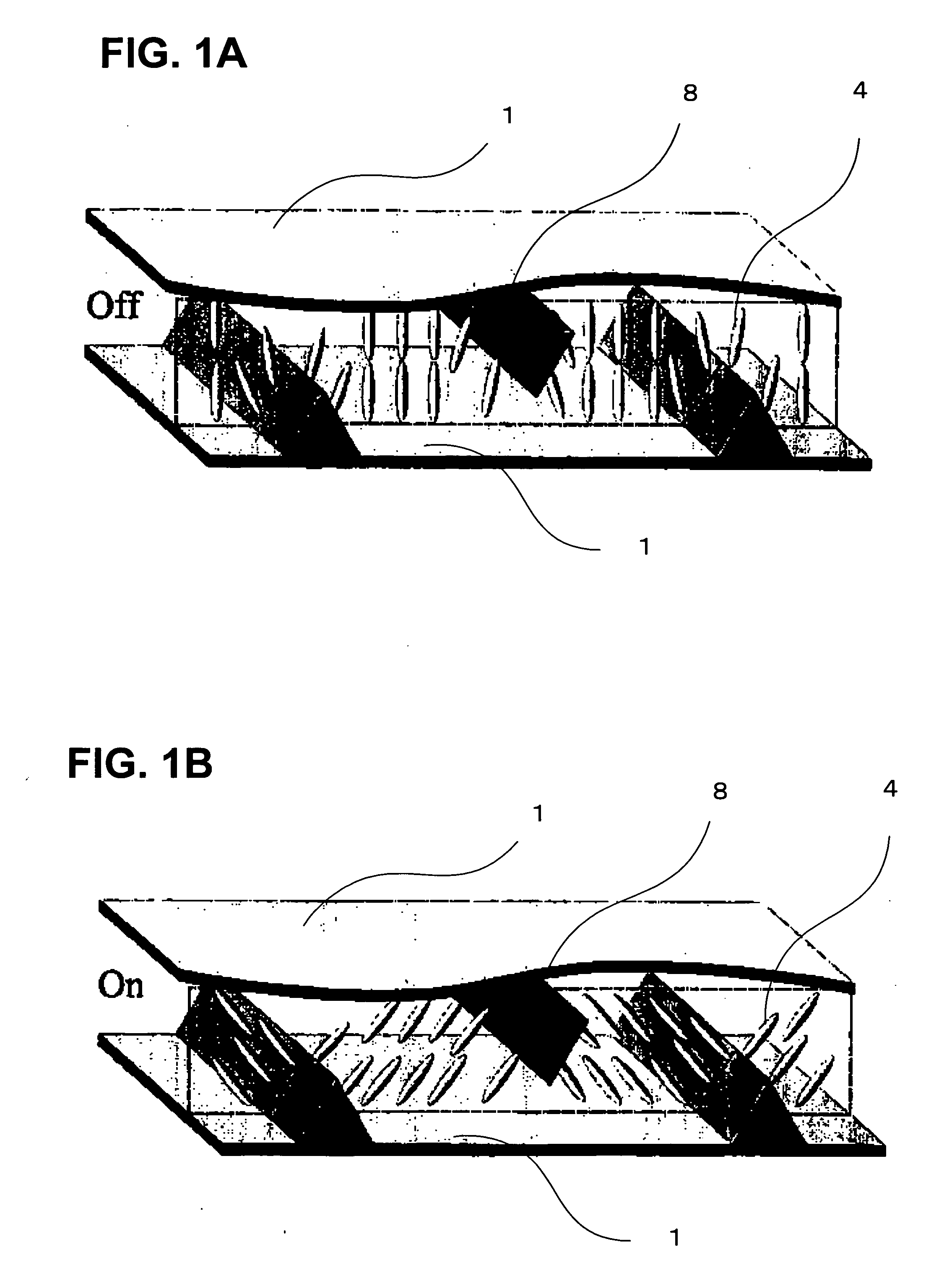
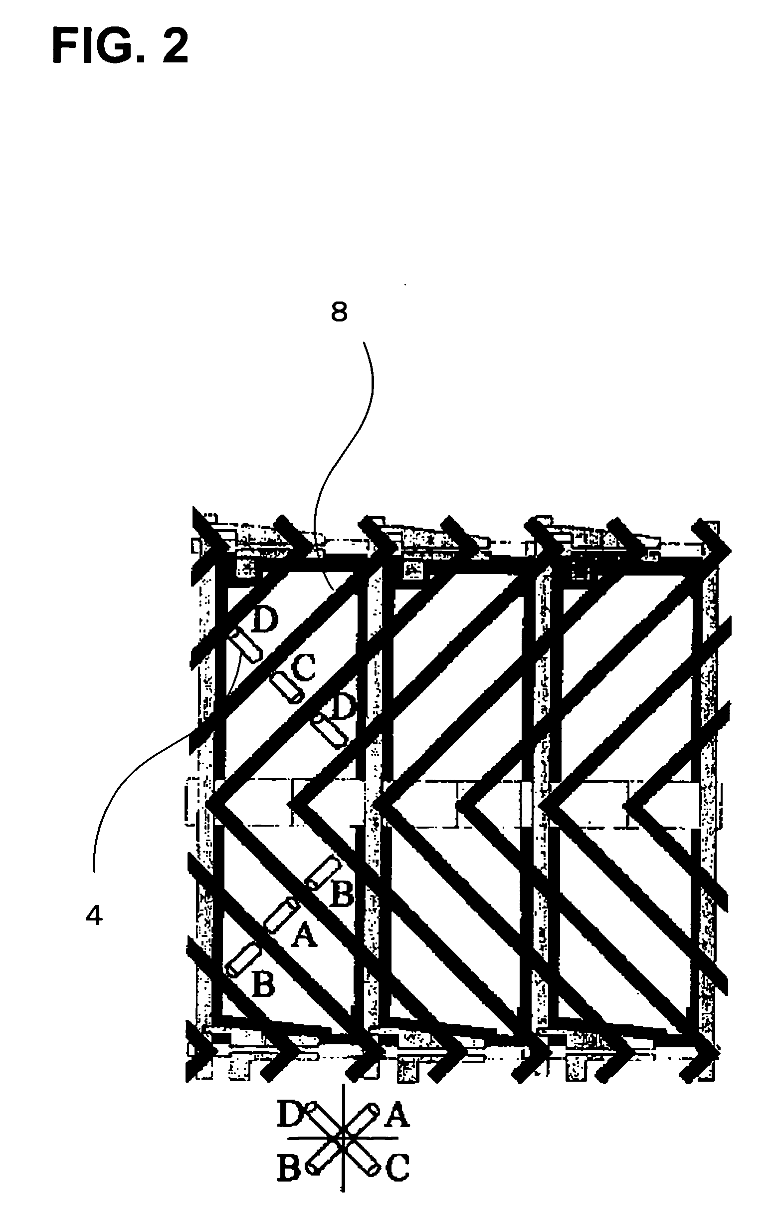
This liquid crystal display device comprises electrodes that are formed on at least one of a pair of substrates, and are used for applying voltage onto liquid crystal molecules; a first alignment control layer that is sandwiched between the substrates, and makes the liquid crystal molecules aligned vertically; a liquid crystal layer formed by sandwiching a liquid crystal composition comprising a liquid crystal and a photopolymerizable compound between the substrates, followed by ultraviolet ray irradiation; and a second alignment control layer composed of a UV-cured product formed by the ultraviolet ray irradiation that is formed so that not less than two domains having different threshold voltages are present in a pixel, and at least one of the domains has a threshold voltage higher than the threshold voltage by the first alignment control layer. Liquid crystal display devices having good half-tone viewing angle characteristics are provided.

Description

CROSS-REFERENCE TO RELATED APPLICATIONS [0001] This application is based upon and claims the benefit of priority from the prior Japanese Patent Application No. 2004-328429, filed on Nov. 12, 2004, the entire contents of which are incorporated herein by reference. BACKGROUND OF THE INVENTION [0002] 1. Field of the Invention [0003] The present invention relates to a liquid crystal display device having improved half-tone viewing angle characteristics. More particularly, the present invention relates to a vertical alignment liquid crystal display device with an improved half-tone viewing angle characteristics such as an MVA (Multi-domain Vertical Alignment) mode liquid crystal display device. [0004] 2. Description of the Related Art [0005] For liquid crystal displays (LCDs) using active matrices, TN mode liquid crystal display devices have been widely used in which a liquid crystal material having a positive dielectric constant anisotropy is aligned horizontally to the substrate surfac...

Claims


Application Information

Patent Timeline
IPC IPC(8): G02F1/1337
CPCG02F1/133753G02F1/133707G02F1/1337
Inventor KATAOKA, SHINGOKOIKE, YOSHIO
Owner SHARP KK
Learn More