Disk array device
a technology of array devices and disk arrays, applied in the field of disk array devices, can solve the problems of failure of hard disk drives, etc., and achieve the effect of preventing the generation of field noise caused by the generation of transitional voltage fluctuations, and ensuring the stability of the array
- Summary
- Abstract
- Description
- Claims
- Application Information
AI Technical Summary
Benefits of technology
Problems solved by technology
Method used
Image

Examples
first embodiment
(1) First Embodiment
(1-1) Exterior Configuration of Disk Array Device in Present Embodiment
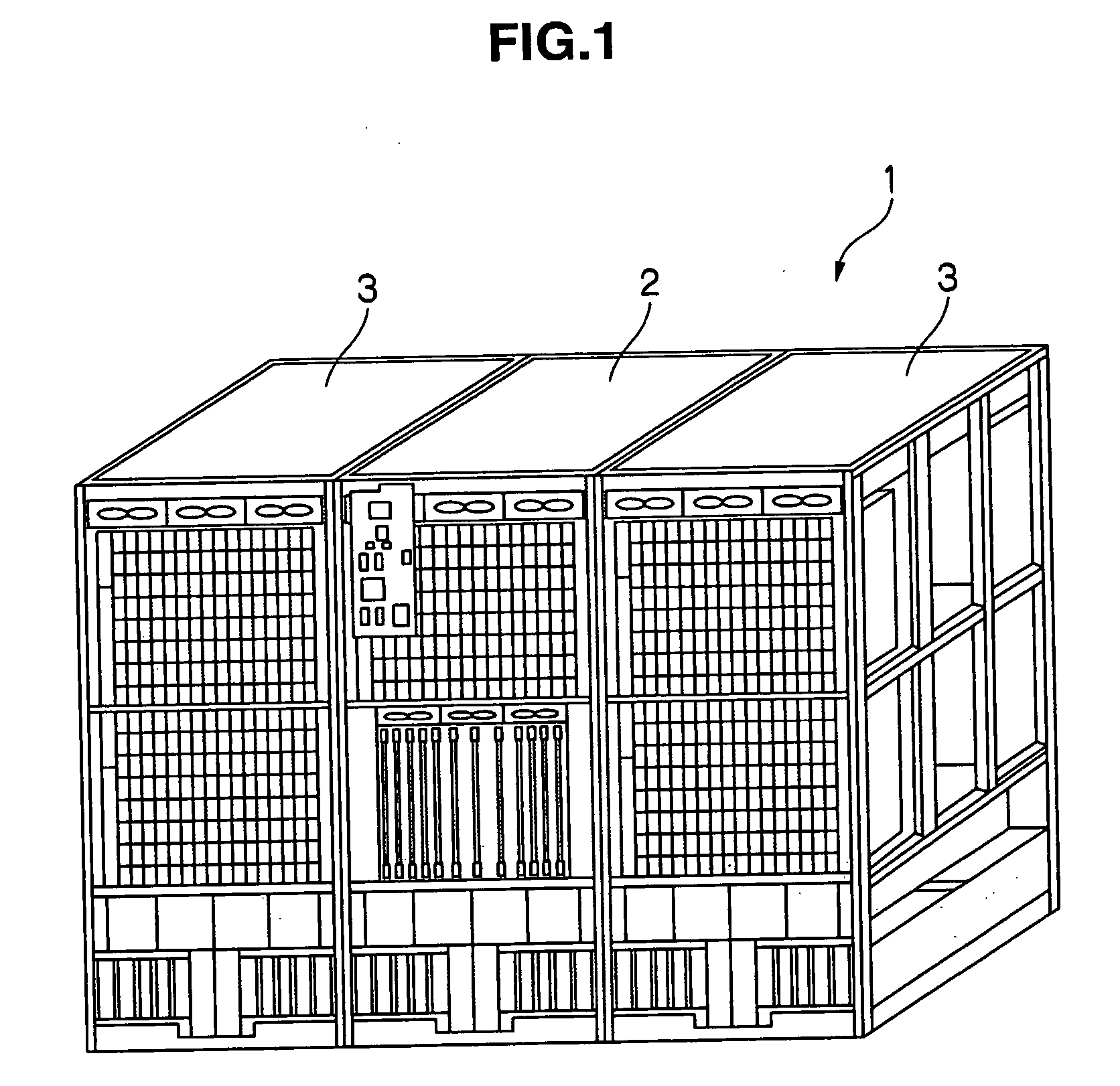
[0043]FIG. 1 to FIG. 4 show the exterior configuration of a disk array device 1 according to the present embodiment. The disk array device 1, as shown in FIG. 1, is configured from a control device 2 and a driver 3.
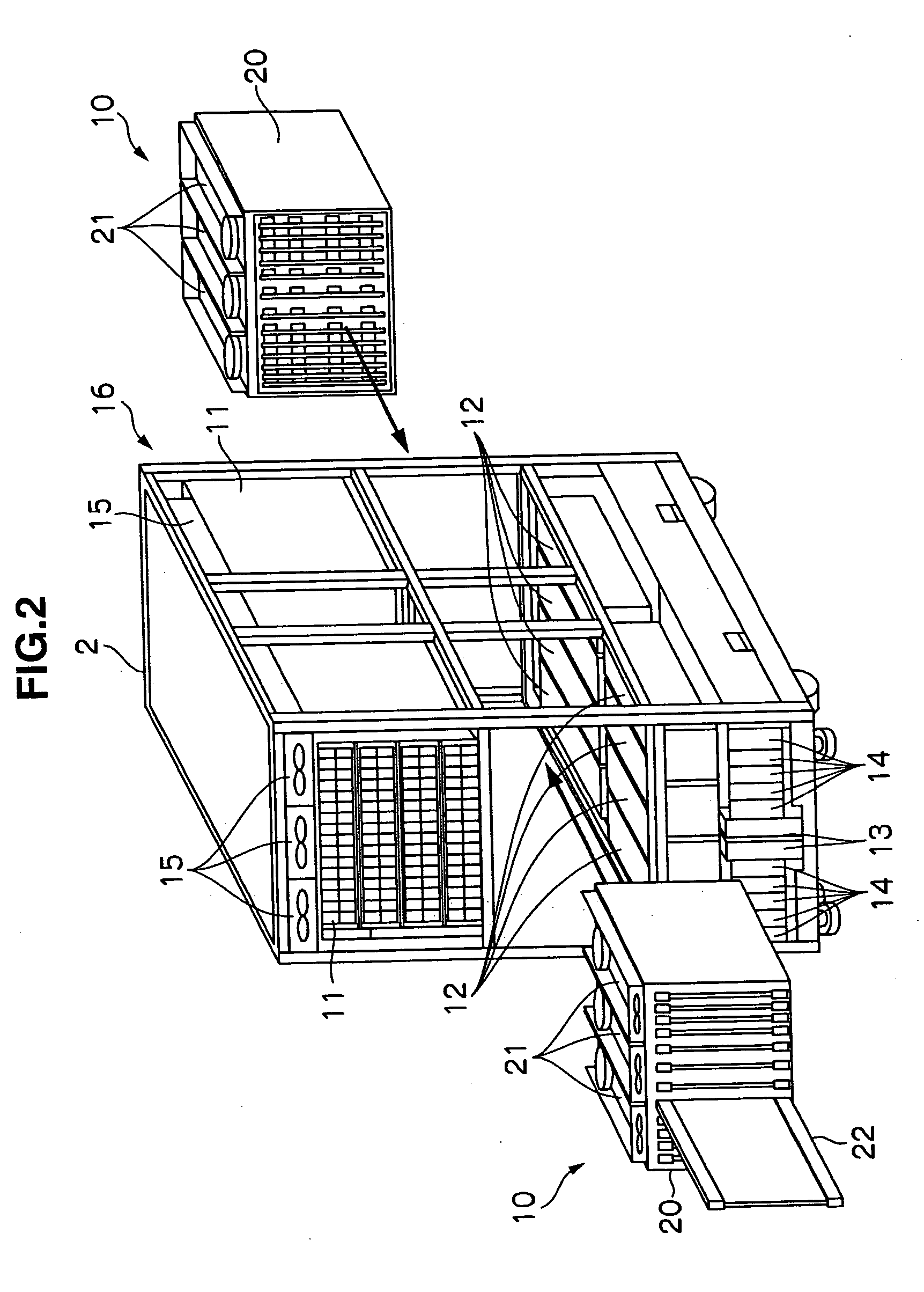
[0044] The control device 2, as shown in FIG. 2 and FIG. 3, is constituted by housing a logical module 10, a hard disk drive module 11, an AC-DC power source 12, an AC-BOX 13, a battery 14 and a fan 15 in a case 16. An operator panel 17 (FIG. 3) to be operated by the operator in charge of the maintenance management of the disk array device 1 is provided to the control device 2.
[0045] As evident from FIG. 2, the logical module 10 has a logical unit 20 for performing the overall control of the disk array device 1, and a logical module fan 21, and is detachably housed in the case 16. A logical board 22 as a control board for performing various control operations relating to the data...
second embodiment
(2) Second Embodiment
[0098] With the DC-DC converter 41 according to the first embodiment described with reference to FIG. 8, two control units of 12V channel and 5V channel (12V channel control circuit 67 and 5V channel control circuit 72) are necessary, and there is a problem in that the circuitry of the DC-DC converter 41 would become complex and increase costs.
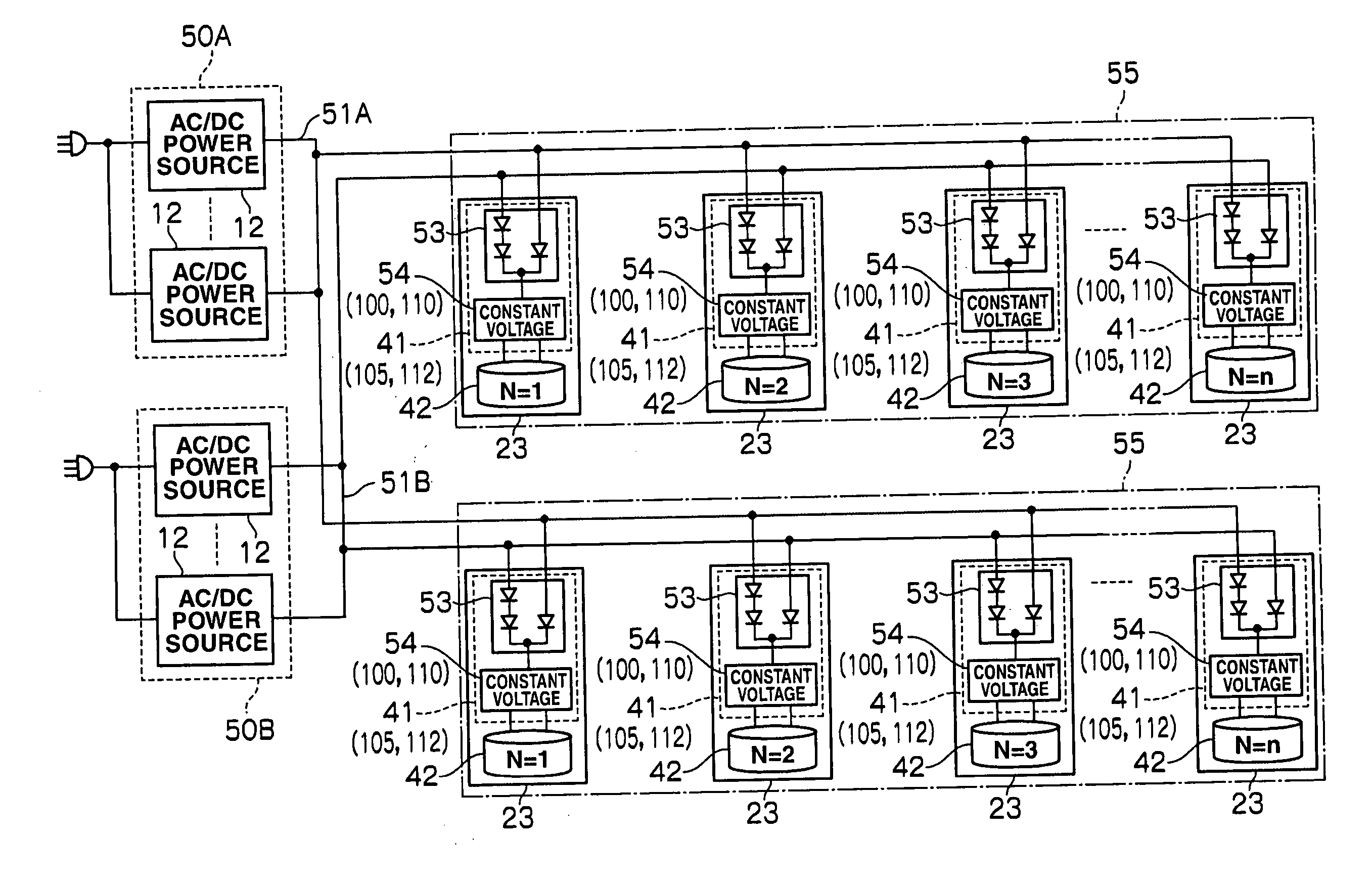
[0099] Thus, the constant voltage circuit of the DC-DC converter 41 may be configured as illustrated in FIG. 11 given the same reference numerals in the components corresponding to those depicted in FIG. 8.
[0100] This constant voltage circuit 80 has two coils; namely, a 12V channel secondary side coil 81A and a 5V channel secondary side coil 81B, as the secondary side coil of the transformer 81 in a power converter 80. Further, the MOS type FET Q1 of the power converter 80 is turned ON / OFF by being PWM controlled by a control circuit 82. Thereby, a 12V induced voltage is generated in the 12V channel secondary side coil 8...
third embodiment
(3) Third Embodiment
[0129]FIG. 20 given the same reference numerals in the components corresponding to those illustrated in FIG. 17 shows a constant voltage circuit 110 according to the third embodiment. With this constant voltage circuit 110, a switch circuit 111 is inserted on the control line of the control circuit 91 in relation to the first and second MOS type FETs Q12, Q13 of the 5V channel rectifier 84.
[0130] The first PWM signal output from the control circuit 91 to be applied to the gate of the first MOS type FET Q12 of the 5V channel rectifier 84 is not passed through this switch circuit 11 during normal operations, and only the second PWM signal output from the control circuit 91 to be applied to the gate of the second MOS type FET Q13 of the 5V channel rectifier 84 is passed therethrough. Accordingly, with the 5V channel rectifier 84, during normal operations, the output voltage output from the 5V channel secondary side coil 81B of the transformer 81 of the power conver...
PUM
| Property | Measurement | Unit |
|---|---|---|
| voltage | aaaaa | aaaaa |
| voltage | aaaaa | aaaaa |
| voltages | aaaaa | aaaaa |
Abstract
Description
Claims
Application Information
 - R&D
- Intellectual Property
- Life Sciences
- Materials
- Tech Scout
- Unparalleled Data Quality
- Higher Quality Content
- 60% Fewer Hallucinations
Browse by: Latest US Patents, China's latest patents, Technical Efficacy Thesaurus, Application Domain, Technology Topic, Popular Technical Reports.
© 2025 PatSnap. All rights reserved.Legal|Privacy policy|Modern Slavery Act Transparency Statement|Sitemap|About US| Contact US: help@patsnap.com