System and process for improving container flow in a port facility

a technology of a port facility and a system is applied in the field of system and process for improving the flow of containers at the port facility, which can solve the problems of high labor intensity, high labor intensity, and high labor intensity of human operators, and achieve the effect of maximizing the efficient use of container transportation equipmen

Active Publication Date: 2006-11-09
APM TERMINALS NORTH AMERICA
View PDF21 Cites 108 Cited by
  • Summary
  • Abstract
  • Description
  • Claims
  • Application Information

AI Technical Summary

Benefits of technology

[0009] This invention meets the foregoing needs and avoids these and other drawbacks and disadvantage of the prior art by providing a port facility equipped to automate container handling through a terminal operating system, which may provide suitable controls for automated routing of container transport vehicles entering the port facility, to provide an improved lane design for efficient movement of containers on land, a regulated access system that allows multiple containers to be transported on land in close proximity to eac

Problems solved by technology

Human operators are prone to make mistakes, especially when tired.
Further, picking a container from a train car or truck chassis, or lowering a container to the same, is difficult and time consuming even in the best of weather, but may be extremely difficult during inclement weather.
In addition, the quay cranes tend not to be used to their fullest operating capacity because the time it takes to load or offload a train car or trailer chassis is longer than the time it takes to transfer a container from ship to shore or vice versa.
Further, significant delays may be experienced if a truck or train malfunctions or is misdirected.
In such instances, the qu

Method used


Image

  • System and process for improving container flow in a port facility
  • System and process for improving container flow in a port facility
  • System and process for improving container flow in a port facility

Examples


Embodiment Construction

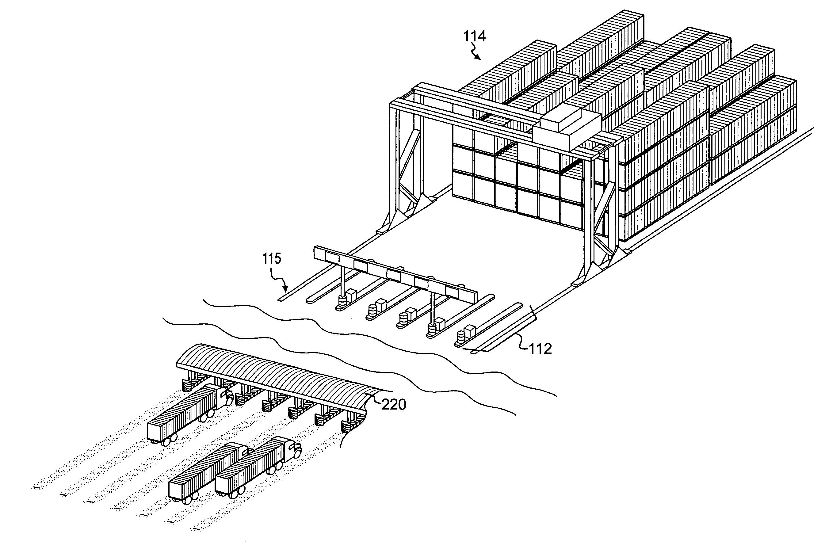
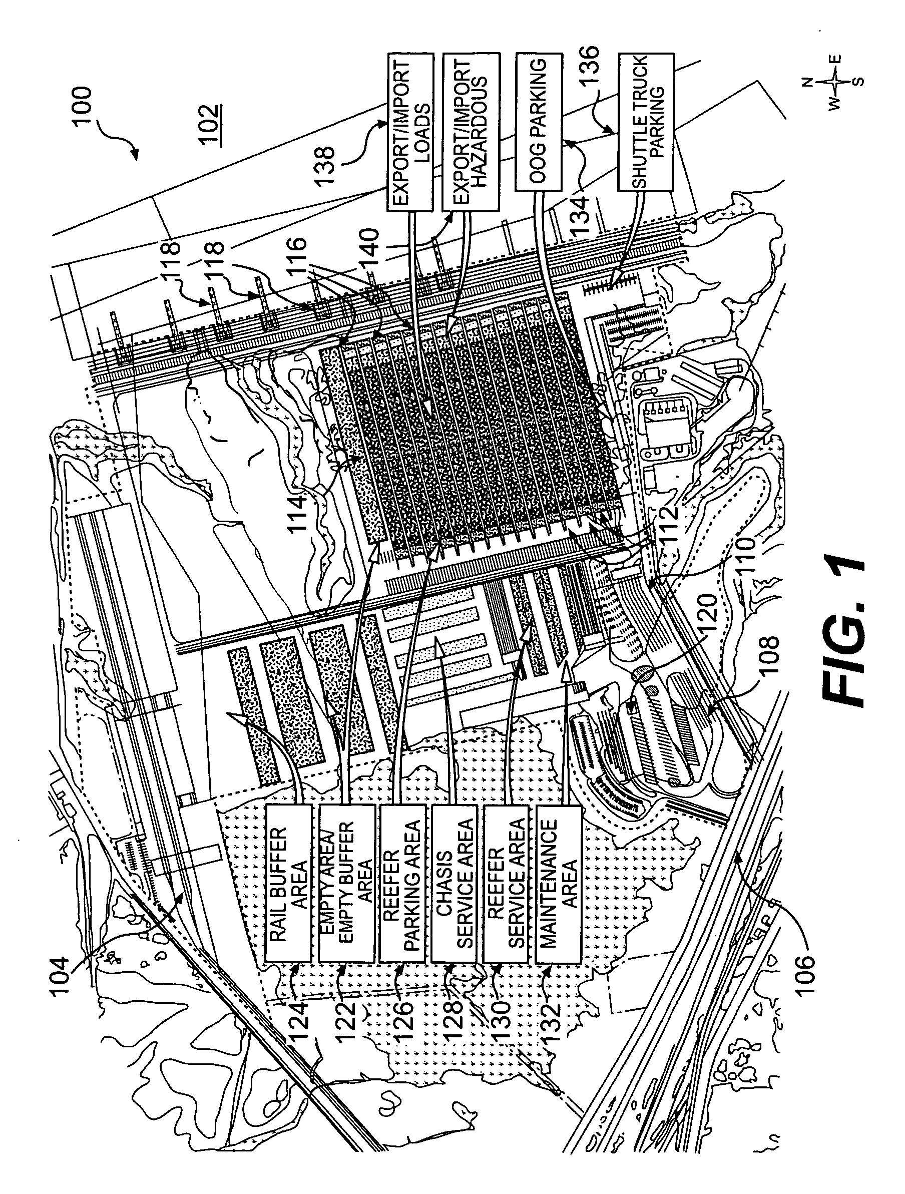
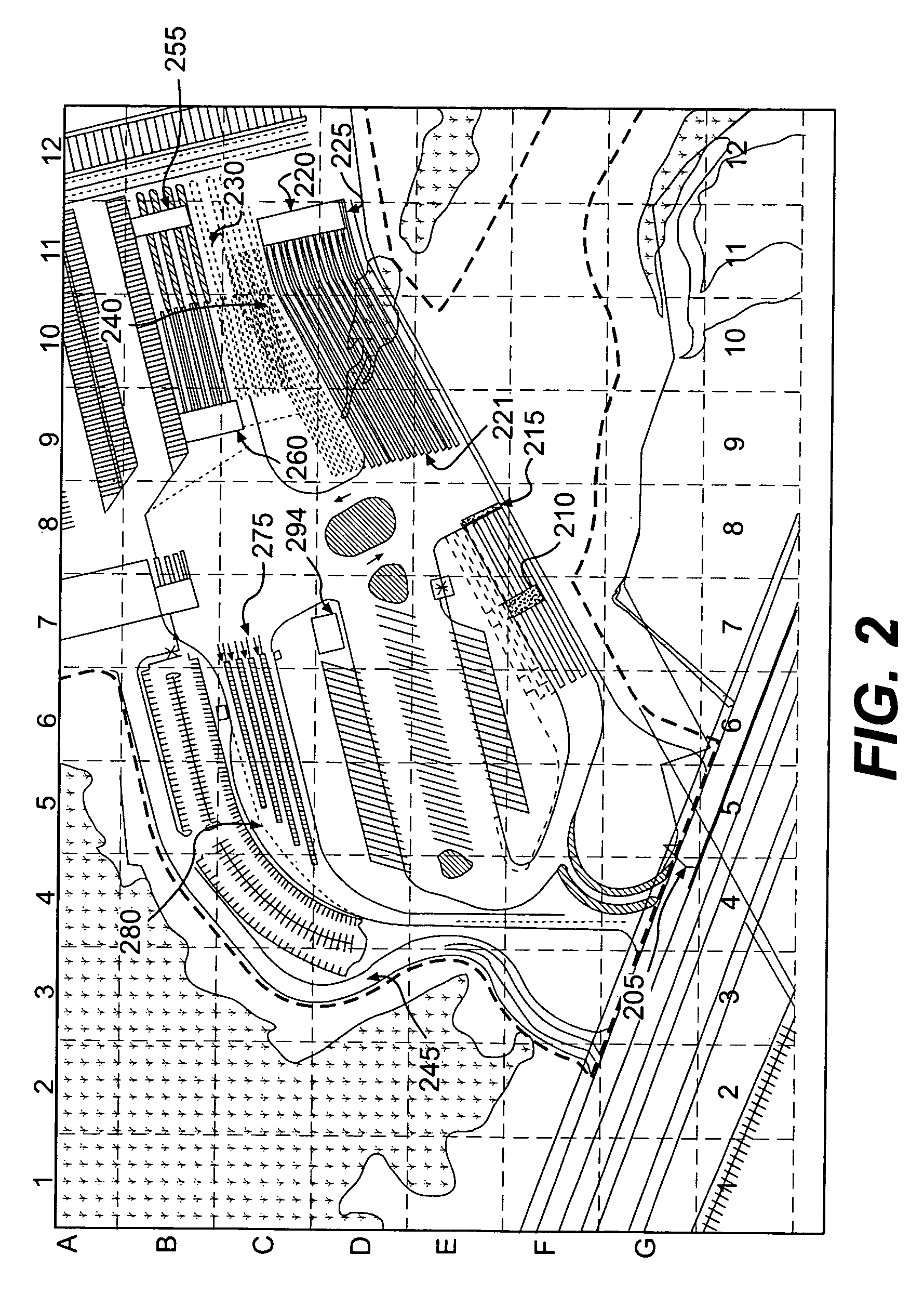
[0046] The embodiments of the invention and the various features and advantageous details thereof are explained more fully with reference to the non-limiting embodiments and examples that are described and / or illustrated in the accompanying drawings and detailed in the following description. It should be noted that the features illustrated in the drawings are not necessarily drawn to scale, and features of one embodiment may be employed with other embodiments as the skilled artisan would recognize, even if not explicitly stated herein. Descriptions of well-known components and processing techniques may be omitted so as to not unnecessarily obscure the embodiments of the invention. The examples used herein are intended merely to facilitate an understanding of ways in which the invention may be practiced and to further enable those of skill in the art to practice the embodiments of the invention. Accordingly, the examples and embodiments herein should not be construed as limiting the ...


PUM


Abstract

A system and process for improving container flow within a port facility, including improved equipment and software for controlling operation and flow of the equipment in the part facility. The system may include a port facility geographically arranged to separate land operations and water operations. Land operations such as over-the-road missions and rail missions may use landside access areas positioned at one end of a yard including rows of container stacks. Water missions such as loading/discharging a vessel may use waterside access areas positioned at the opposite end of the yard. Automated cranes linked with a terminal operating system may pick/drop/shuffle containers and/or refrigerated containers (“reefers”) within the container stacks. Shuttle trucks may be used to pick/drop containers at quayside access points and the waterside access areas. The shuttle trucks may utilize shared wheelpaths. Software systems may be used to implement various principles of the invention.

Description

CROSS-REFERENCE TO RELATED APPLICATIONS [0001] This application claims priority under 35 U.S.C. § 119(e) to U.S. Provisional Application No. 60 / 655,876 filed on Feb. 25, 2005, the disclosure of which is hereby incorporated by reference in its entirety.BACKGROUND OF THE INVENTION [0002] 1 Field of Invention [0003] The field of invention relates generally to the transport of freight containers, and more particularly, to a system and process for improving container flow at a port facility, as well as improved equipment and / or software for use in such a facility. [0004] 2 Background Description [0005] Freight containers have been used for many years to transport dry and refrigerated goods across the world's oceans, or land. For local land moves, metal containers, which may range in size from 20′ to 45′ and can carry loads ranging up to 85,000 lbs., are carried on trailer chassis which are towed by semi-tractors. For long distance land moves, the containers are stacked on flatbed railroa...

Claims


Application Information

Patent Timeline
IPC IPC(8): B65G67/60G06Q10/00
CPCB65G63/004B66C13/48G06Q10/08B66C19/002G06Q10/06B66C17/20
Inventor BUZZONI, GUY ALANHUDSON, RICHARD L.MCCARTHY, EDWARDGIUGLIANO, PETER
Owner APM TERMINALS NORTH AMERICA
Why Eureka
Try Eureka