Thermocline thermal energy storage in multiple tanks

a technology of thermal energy storage and multiple tanks, which is applied in the field of energy storage, can solve the problems of difficult to maintain the initial design width the inability of solar mirror arrays to heat the thermal energy storage fluid, and the widening so as to maximize the efficient use of available energy and minimize the degradation of the thermocline zone

Active Publication Date: 2022-03-31
TERRAFORCE TECH LLC
View PDF0 Cites 0 Cited by
  • Summary
  • Abstract
  • Description
  • Claims
  • Application Information

AI Technical Summary

Benefits of technology

[0014]Embodiments of the present disclosure provide a thermal energy storage system for optimally designing and automatically managing a thermocline zone using multiple tanks connected in series to achieve the effect of a single tall tank (i.e., a tank having a high tank height to diameter ratio). The use of multiple tanks in this manner enables the reestablishment of a thermocline zone each time the thermocline passes through the bottom or top of a tank, thereby minimizing degradation of the thermocline zone during charging and discharging. Additionally, during charging, the thermal energy storage system can draw thermal storage fluid from multiple tanks to ensure that the fluid is cool enough to maximize efficient use of available energy during charging, particularly as the thermocline approaches the bottom of each of the tanks during the charging process.

Problems solved by technology

Unfortunately, when the sun is not available, solar mirror arrays are unable to heat the thermal energy storage fluid.
One shortcoming of thermocline energy storage is that it is difficult to maintain this initial design width of the thermocline zone in the storage tank.
This is because, the process of repeatedly extracting cold fluid from the tank and returning hot fluid to the top during the charge and discharge process, results in the widening of the thermocline zone.
This widening, referred to as the degradation of the thermocline, causes a decrease in the storage capacity or utilization factor.
In addition to the repeated charge and discharge cycles, there are other factors that cause degradation of thermocline, such as conduction between layers, mixing of fluid due to turbulence when fluid is extracted from the tank or added to the tank, and mixing as a result of an increase in the velocity of the fluid.
This approach, however, adds significantly to the overall complexity and cost of the thermal energy system.

Method used


Image

  • Thermocline thermal energy storage in multiple tanks
  • Thermocline thermal energy storage in multiple tanks
  • Thermocline thermal energy storage in multiple tanks

Examples


Embodiment Construction

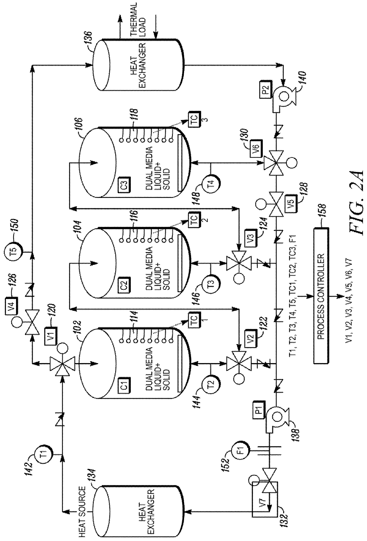
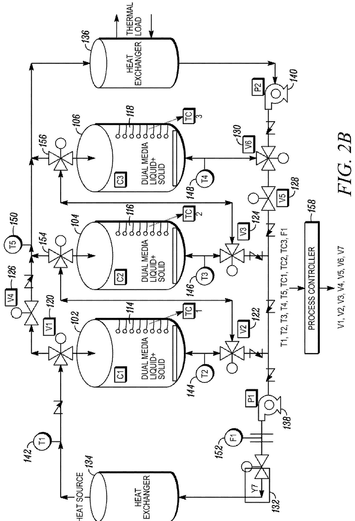
[0037]Referring to FIG. 2A, an illustration of a thermal storage system 100 is depicted in accordance with an embodiment of the disclosure. The thermal energy storage system 100 can include multiple storage tanks configured to store thermal energy storage fluid. Although three storage tanks 102, 104, 106 are depicted, a greater or lesser number of storage tanks are also contemplated. For example, in one embodiment, the thermal energy storage system 100 could utilize four storage tanks.

[0038]In one embodiment, the thermal storage fluid can be a dual-media of solid and liquid. In one embodiment, the solid can be comprised of particles and can be made from materials such as rock, quartzite, granite, or ceramic pebbles. In another embodiment, the solid particles can be small generally spherically shaped capsules containing a phase change salt, configured to store thermal energy via a phase change. In one embodiment, the solid particles can have a diameter or cross-sectional width of abo...


PUM


Abstract

A method of optimizing thermocline zone within a thermal storage system including a plurality of storage tanks fluidly coupled to one another m series, to effectively form a single tank having an equivalent height of the combined height of the plurality of storage tanks. The method including identifying a thermocline zone, computing an average temperature (Tave) of the thermocline zone, directing thermal storage fluid from a bottom of an initial storage tank through a heat source heat exchanger, and terminating fluid flow from the bottom of the initial storage tank and directing thermal storage fluid from a bottom of a first subsequent storage tank when a temperature of the thermal storage fluid exiting the bottom of the initial storage tank reaches Tave.

Description

TECHNICAL FIELD[0001]The present disclosure relates generally to energy storage, and more particularly to a system and method for improving the efficiency of a thermal energy storage system by utilizing a plurality of tanks connected in series to minimize degradation of a thermocline zone during charging and discharging, and to maximize the capacity to store energy.BACKGROUND[0002]Worldwide, there is an ever-growing demand for electricity due to increasing populations and technology advancements that require the use of electricity. At the same time, there is an increasing push to harness renewable resources of energy to help meet these increasing electricity demands to offset and / or replace traditional carbon-based energy plants, which rely on depleting natural fossil fuel resources and contribute to pollution and global warming.[0003]Many solutions have been developed to collect and take advantage of renewable sources of energy, such as solar collectors, bio-gas boilers, etc. Solar...

Claims


Application Information

Patent Timeline
Patent Type & Authority Applications(United States)
IPC IPC(8): F28D20/02F28D20/00
CPCF28D20/023F28D2020/0082F28D20/0056F28D20/0034Y02E60/14F28D20/0039
Inventor MATHUR, ANOOP
Owner TERRAFORCE TECH LLC
Why Eureka
Try Eureka