

Miniaturized gas sensors featuring electrical breakdown in the vicinity of carbon nanotube tips
a carbon nanotube tip and gas sensor technology, applied in the field of gas sensors, can solve the problems of high power consumption, risky high-voltage operation, and limited sensor rang
- Summary
- Abstract
- Description
- Claims
- Application Information
AI Technical Summary
Benefits of technology
Problems solved by technology
Method used
Image

Examples
Embodiment Construction
[0022] Unless otherwise indicated, “a” or “an” means “one or more”.
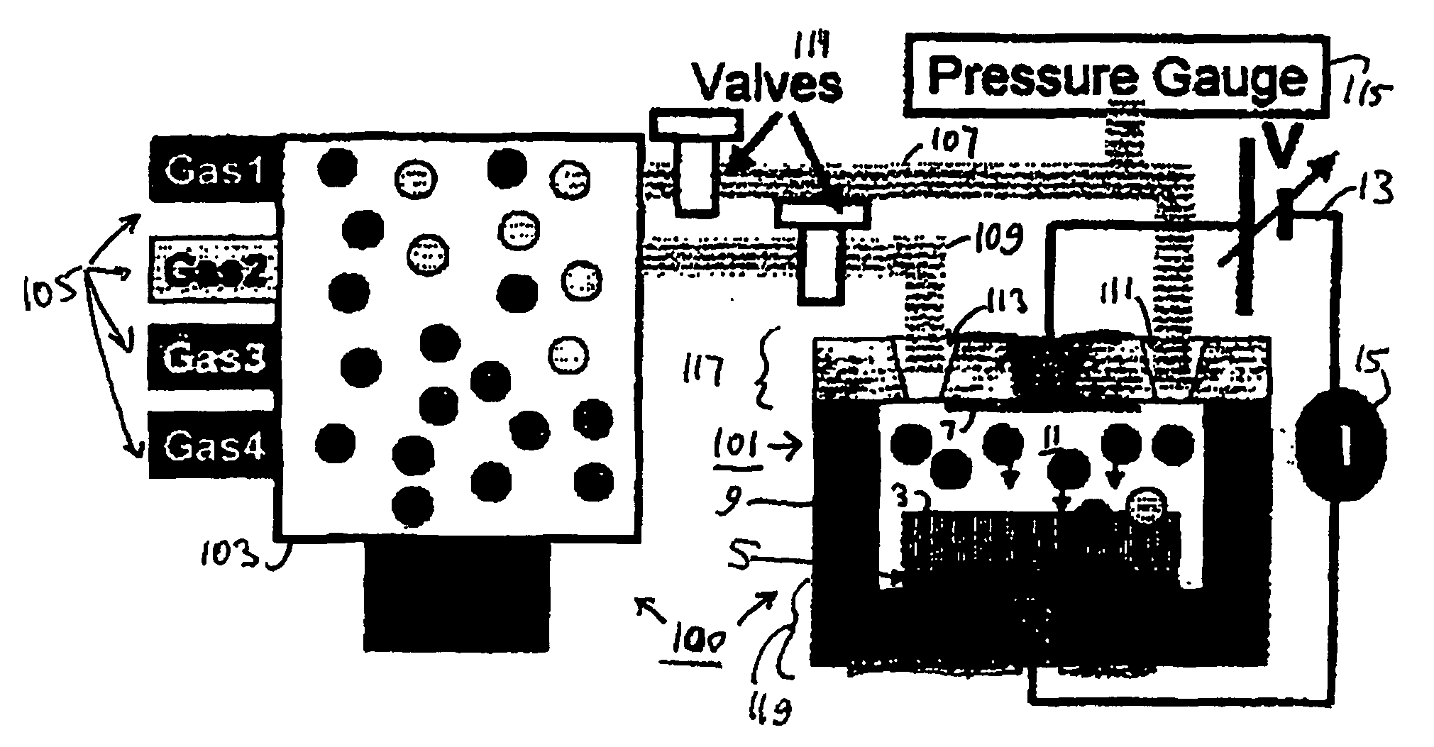
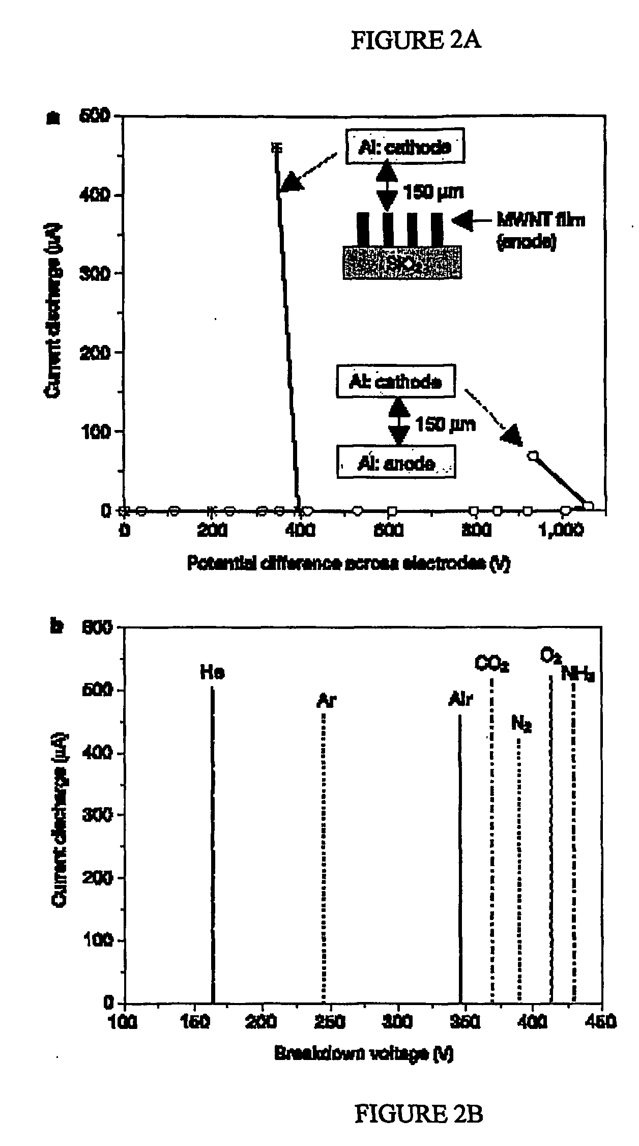
[0023] The preferred embodiments of the present invention provide an ionization gas sensor that overcomes some of the limitations described in the previous section. The ionization microsensor uses the extremely high electric fields that are generated near nanotube tips as a means of inducing electrical breakdown of the analyte gas at relatively low voltages. The sensor may be used to determine the species and / or the concentration of a range of gases and gas mixtures the are broken down at the carbon nanotube tips.
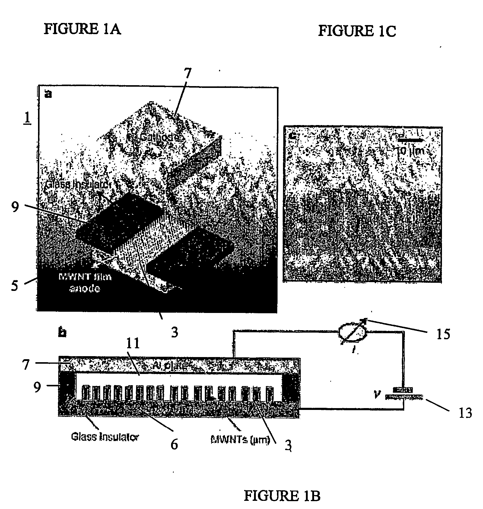
[0024] The sensor contains an electrode comprising nanotubes that are formed in a shape of a film. The nanotubes in the film are densely packed and the inter-tube tunneling effects result in the aggregate nanotube film behaving like a conducting sheet electrode. Thus, the sensor includes a nanotube electrode with a high density and uniformity and a comparatively large sensing area. The nanotube electrode i...
PUM
| Property | Measurement | Unit |
|---|---|---|
| volume | aaaaa | aaaaa |
| volume | aaaaa | aaaaa |
| voltage | aaaaa | aaaaa |
Abstract
Description
Claims
Application Information