Composite pre-formed construction articles

a technology of pre-formed construction and construction articles, applied in the field of pre-formed building and construction panels, can solve the problems of insufficient capacity of construction elements made of expanded plastics to securely hold the outer covering layer, flow and burn,

Inactive Publication Date: 2006-11-09
SYNTHEON HLDG SPA
View PDF99 Cites 40 Cited by
  • Summary
  • Abstract
  • Description
  • Claims
  • Application Information

AI Technical Summary

Benefits of technology

[0043] The present invention is further directed to buildings that contain one or more of the above-des...

Problems solved by technology

While the construction elements described above have on the one hand a light weight, a comparative ease of installation and a low cost, on the other hand their application in the art and flexibility of use have been restrained heretofore by their poor fire-resisting properties and/or the propensity for mold to grow on finished surfaces attached thereto.
This inadequate resistance to fire is essentially related to the fact that construction elements made of expanded plastics show an insufficient capability to securely hold outer covering layers, such as the plaster layers used for the outer surface finish or contain the expanded polymer body, in flammable molten or liquid form, that occurs from the heat generated from a fire.
When exposed to fire, in fact, the expanded plastics soon shrink into a shapeless mass of reduced volume, which can flow and burn, and in some cases with the ensuing separation of the outer covering layers and rapid collapse of the whole structure.
In addition, an undesirable separation of the outer covering layers may be caused in some instances by a premature “aging” of the plastics surface to which these coverings adhere, a separation which may be further fostered by exposure to heat sources, dusts, fumes, vapors, or chemical substances coming from a source close to the construction elements.
However, moisture buildup between the lath and construction element can lead to mold and mildew growth and the ability to easily run electrical lines without cutting into the construct...

Method used


Image

  • Composite pre-formed construction articles
  • Composite pre-formed construction articles
  • Composite pre-formed construction articles

Examples


Embodiment Construction

[0086] For the purpose of the description hereinafter, the terms “upper,”“lower,”“inner”, “outer”, “right,”“left,”“vertical,”“horizontal,”“top,”“bottom,” and derivatives thereof, shall relate to the invention as oriented in the drawing Figures. However, it is to be understood that the invention may assume alternate variations and step sequences except where expressly specified to the contrary. It is also to be understood that the specific devices and processes, illustrated in the attached drawings and described in the following specification, is an exemplary embodiment of the present invention. Hence, specific dimensions and other physical characteristics related to the embodiment disclosed herein are not to be considered as limiting the invention. In describing the embodiments of the present invention, reference will be made herein to the drawings in which like numerals refer to like features of the invention.

[0087] Other than where otherwise indicated, all numbers or expressions ...


PUM

PropertyMeasurementUnit
Timeaaaaaaaaaa
Thicknessaaaaaaaaaa
Thicknessaaaaaaaaaa

Abstract

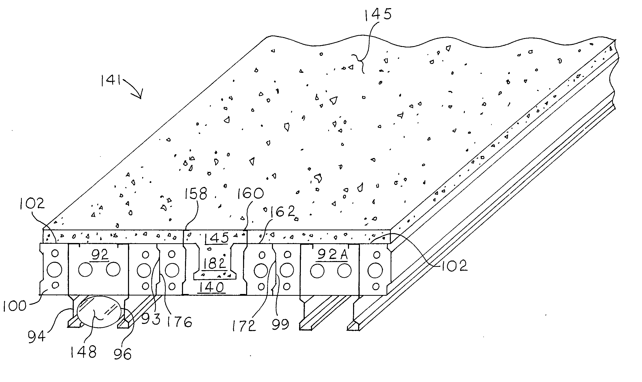
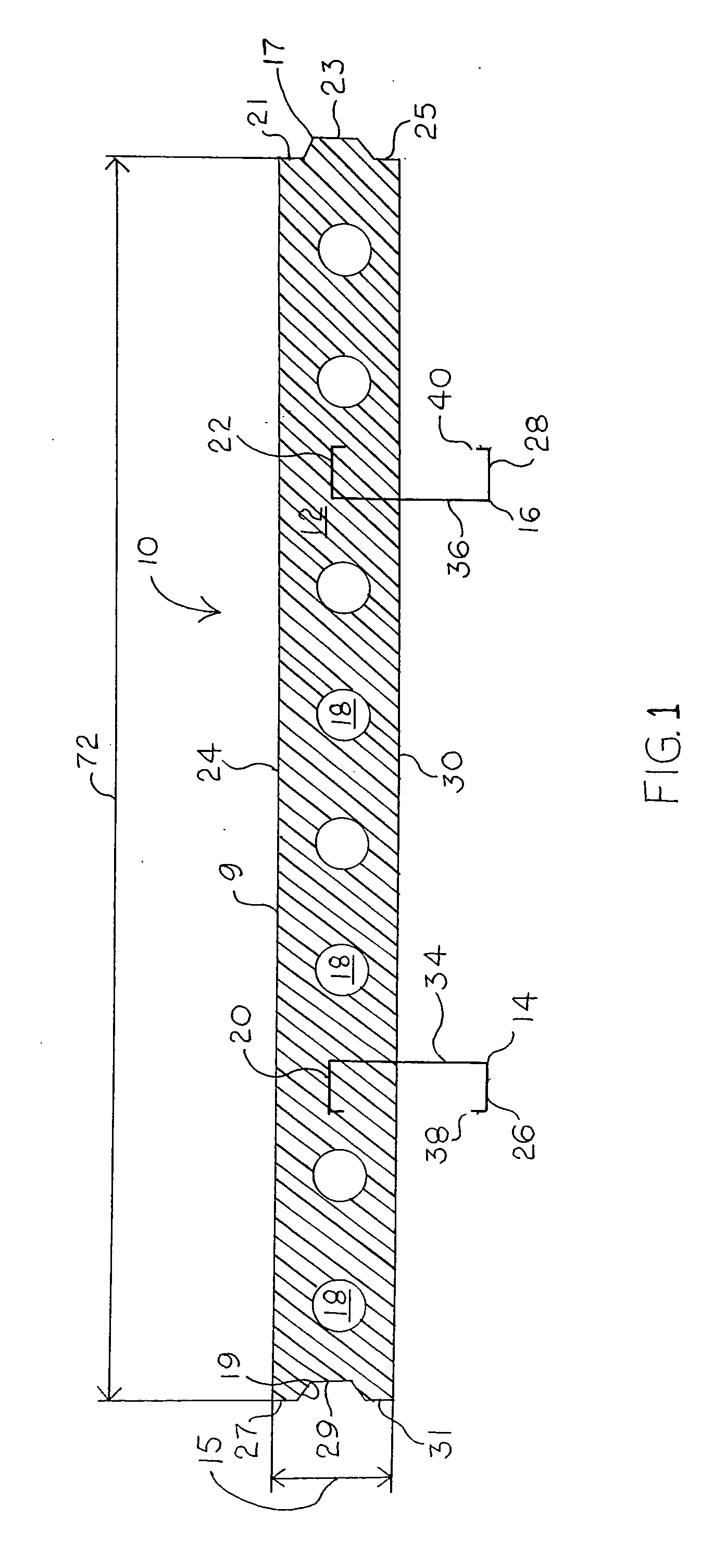
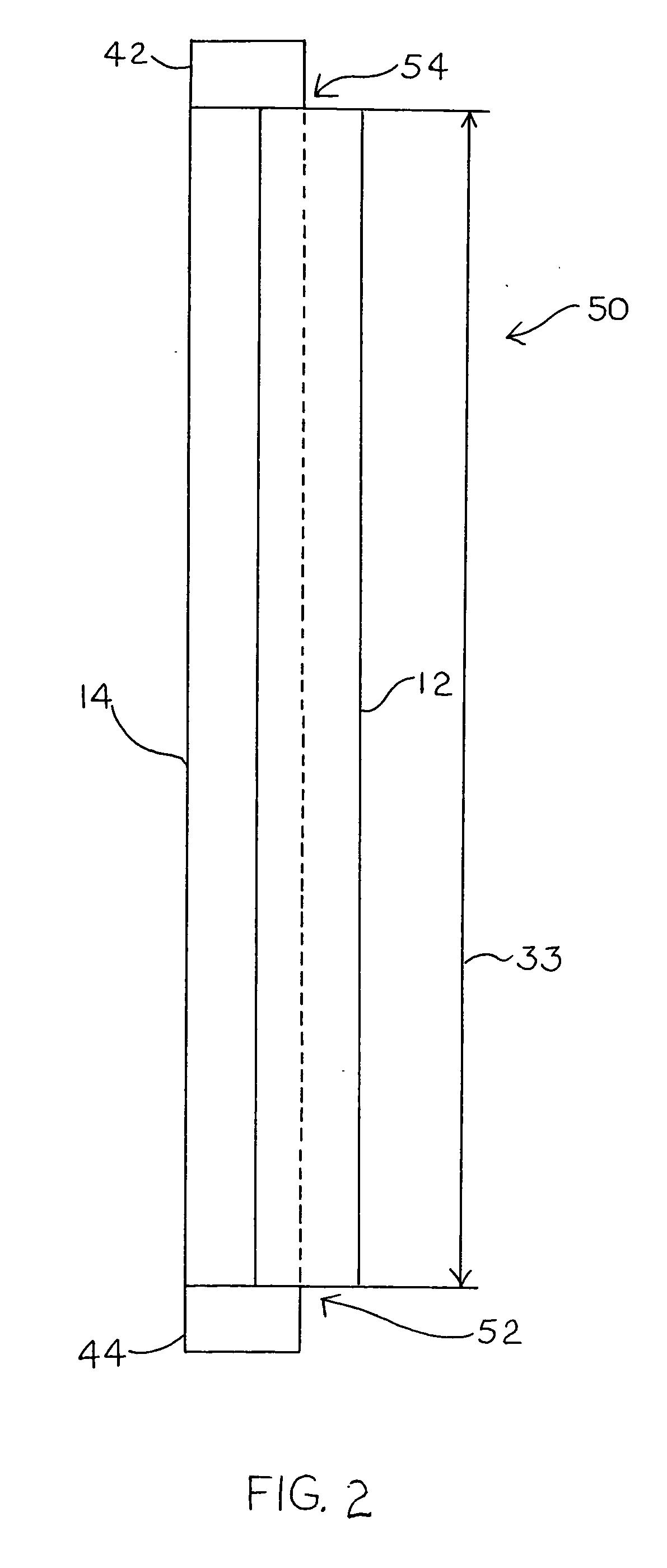
A composite building panel that includes a central body, substantially parallelepipedic in shape, containing an expanded polymer matrix, having opposite faces, a top surface, and a bottom surface; at least one embedded framing stud longitudinally extending across the central body between the opposite faces, having a first end embedded in the expanded polymer matrix, a second end extending away from the bottom surface of the central body, and one or more expansion holes in the embedded studs between the first end of the embedded stud and bottom surface through which the polymer matrix expands. A concrete layer can optionally cover a portion of the top surface and/or bottom surface. The building panel can be positioned perpendicular to a structural wall and/or foundation to provide a floor panel. The second end of the framing studs can be embedded in a second central body to provide an insulated concrete form.

Description

REFERENCE TO RELATED APPLICATION [0001] This application claims the benefit of priority of U.S. Provisional Application Ser. Nos. 60 / 656,596 filed Feb. 25, 2005 and 60 / 664,120 filed Mar. 22, 2005, both entitled “Composite Pre-Formed Building Panels” and U.S. Provisional Application Ser. No. 60 / 728,839 filed Oct. 21, 2005 entitled “Composite Pre-Formed Insulated Concrete Forms,” which are all herein incorporated by reference in their entirety.BACKGROUND OF THE INVENTION [0002] 1. Field of the Invention [0003] The present invention is directed to pre-formed building and construction panels that include one or more reinforcing structural elements embedded in a foamed thermoplastic matrix as well as insulated concrete forms with internal blocking and bracing elements. [0004] 2. Description of the Prior Art [0005] It is known to use construction elements made of expanded plastics, for example expanded polystyrene, in forms of boards or section members of suitable shape and size. These me...

Claims


Application Information

Patent Timeline
IPC IPC(8): B32B3/00B32B5/14
CPCE04B5/043Y10T428/233B32B3/06B32B3/26B32B3/263B32B3/266B32B13/00B32B15/08B32B15/10B32B15/18B32B15/20B32B21/08B32B27/08B32B27/302B32B27/308B32B27/32B32B27/365B32B27/42B32B2307/3065B32B2307/546B32B2307/558B32B2307/71B32B2419/04B32B2607/00Y10T428/269E04B5/06Y10T428/24996
Inventor BOWMAN, JAY
Owner SYNTHEON HLDG SPA
Why Eureka
Try Eureka