Operational control device, operational control method, program and storage medium thereof, for a plurality of power consumption systems

a power consumption system and control device technology, applied in the direction of process and machine control, screws, instruments, etc., can solve the problems of not always driving at the normal rated power of all processing equipments, affecting the efficiency of the operation of the operation, and consuming a large amount of electric power for each processing equipment. , to achieve the effect of enhancing productivity relative to equipment cost and high operating efficiency

Inactive Publication Date: 2006-11-09
TOKYO ELECTRON LTD
View PDF4 Cites 14 Cited by
  • Summary
  • Abstract
  • Description
  • Claims
  • Application Information

AI Technical Summary

Benefits of technology

[0011] The present invention was made in the light of the above-described problems, and is constructed to effectively overcome the same. It is an object of the present invention to provide an operational control device, an operational control method, a program and a storage medium thereof, for a plurality of power consumption systems, which can establish a high operating efficiency while controlling the equipment cost.
[0013] In such a manner, a power consumption pattern that indicates changes in the power consumption of each power consumption system is obtained in advance. When a request for starting operation is made by an idling power consumption system, power consumption patterns of power consumption systems each operating at that time are summed together with adjustment of the axis of time to obtain a combined expected power consumption pattern. Then, the power consumption pattern of the idling power consumption system which has made the request for starting operation is added to the combined expected power consumption pattern to obtain a combined assumed power consumption pattern. Subsequently, the combined assumed power consumption pattern obtained by the addition is compared to a preset allowable electric power. Finally, the power consumption pattern of the idling power consumption system which has made a request for starting operation is shifted in the direction of the axis of time to determine an expected operational start time. Therefore, high operating efficiency can be achieved while controlling the equipment cost. In addition, the productivity relative to the equipment cost can be enhanced to the maximum.
[0031] With the operational control device, the operational control method and the storage medium, according to the present invention, the following effects can be obtained.
[0032] A power consumption pattern that indicates changes in the power consumption of each power consumption system is obtained in advance. When a request for starting operation is made by an idling power consumption system, power consumption patterns of power consumption systems each operating at that time are summed together with adjustment of the axis of time to obtain a combined expected power consumption pattern. Then, the power consumption pattern of the idling power consumption system which has made the request for starting operation is added to the combined expected power consumption pattern to obtain a combined assumed power consumption pattern. Subsequently, the combined assumed power consumption pattern obtained by the addition is compared to a preset allowable electric power. Finally, the power consumption pattern of the idling power consumption system which has made a request for starting operation is shifted in the direction of the axis of time to determine an expected operational start time. Therefore, high operating efficiency can be achieved while controlling the equipment cost. In addition, the productivity relative to the equipment cost can be enhanced to the maximum.

Problems solved by technology

For wafers and LCD substrates, since heating and plasma processes are mainly performed, each processing equipment consumes relatively a large amount of electric power.
In addition, power supply equipments for supplying electric power to those units are relatively expensive.
However, all processing equipments are not always driven at the normal rated power.
In fact, the time for which they are driven at the normal rated power is relatively short.
Accordingly, the above prior art power supply equipments should have significantly large margin of the power capacity, thus leading to increase in the cost of such power supply equipments and increase in the contract rate to the electric power company.
However, since these prior art methods did not consider any change in the amount of power consumption over time for each processing equipment, so once a process was started, such a change in the amount of power consumption along the proceeding of the process of each processing equipment was not controlled enough.

Method used


Image

  • Operational control device, operational control method, program and storage medium thereof, for a plurality of power consumption systems
  • Operational control device, operational control method, program and storage medium thereof, for a plurality of power consumption systems
  • Operational control device, operational control method, program and storage medium thereof, for a plurality of power consumption systems

Examples


examples

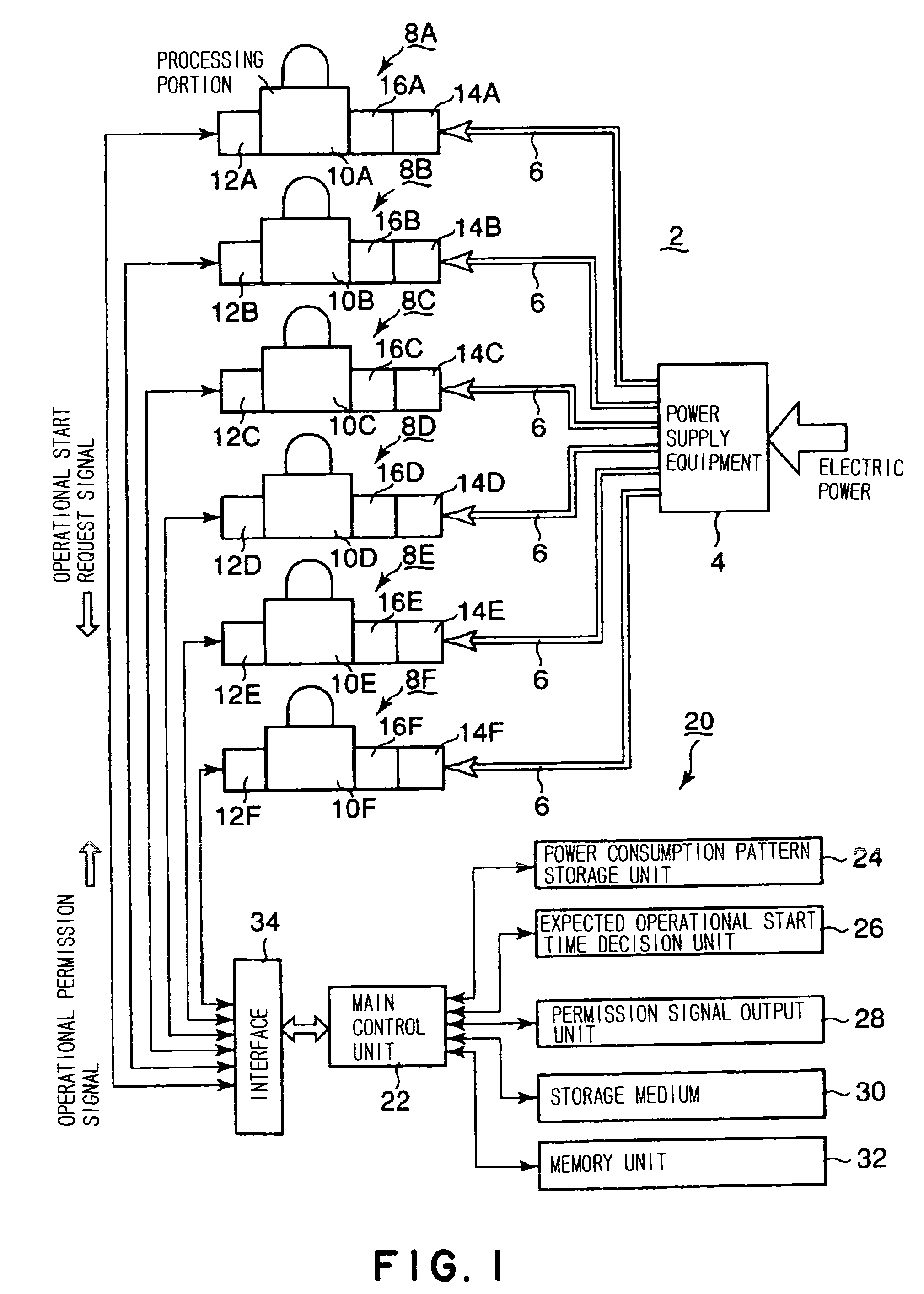
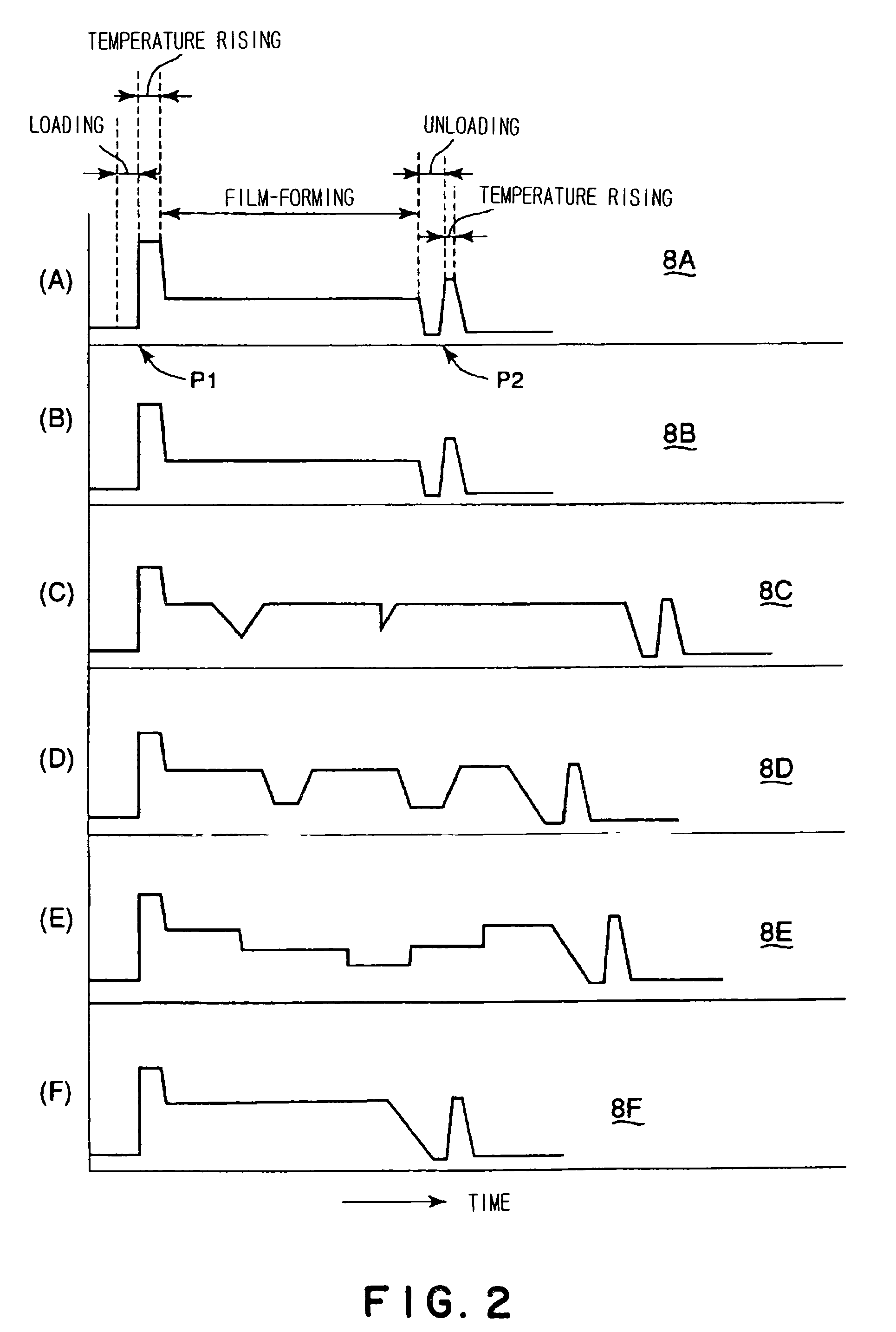
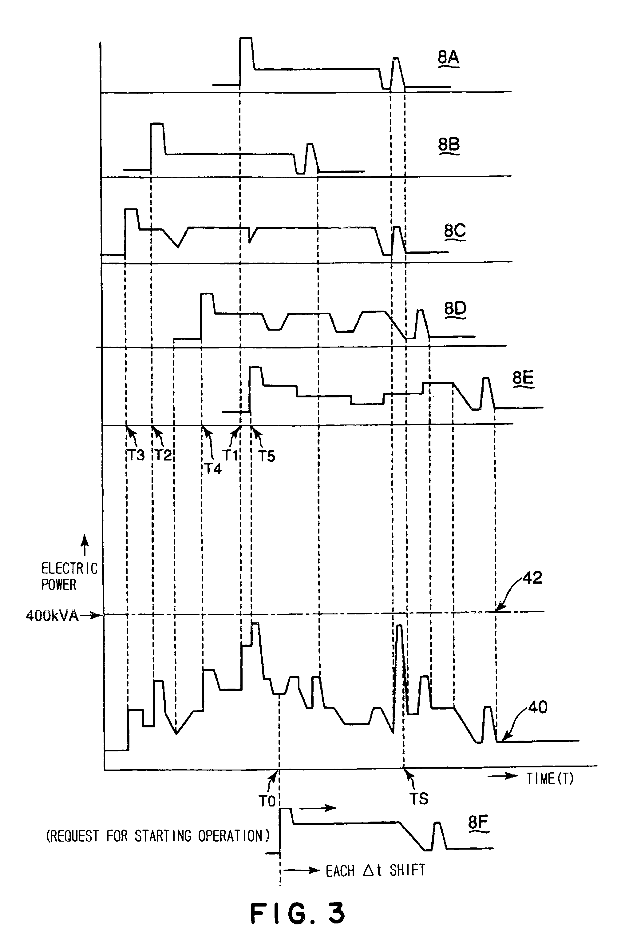
[0038]FIG. 1 is a view of illustrating a relation between an operational control device, for a plurality of power consumption systems according to the present invention, and a power supply system, FIG. 2 is a view of illustrating a power consumption pattern of each of power consumption systems, and FIG. 3 is a view of illustrating a state resulting from arranging and adding each of operating power consumption patterns based on each operational start time.

[0039] As shown in FIG. 1, a power supply system 2 comprises a power supply equipment 4, from which necessary electric power is supplied to a plurality of power consumption systems (in the illustrated embodiment, shown as six processing equipments 8A, 8B, 8C, 8D, 8E, and 8F), via power lines 6, respectively.

[0040] As each of the processing equipments 8A to 8F as the above power consumption systems, a processing equipment for providing a predetermined process to materials to be processed, for example, semiconductor wafers, is used,...


PUM


Abstract

In an operational control device 20 of a power supply system for supplying electric power from an electric power equipment 4 to a plurality of power consumption systems 8A to 8F, a power consumption pattern of each of the power consumption systems is stored, and a combined expected power consumption pattern 40 is obtained by adding together power consumption patterns of operating power consumption systems. Next, a combined assumed power consumption pattern is obtained by adding a power consumption pattern, obtained based on a temporary operational start time, of a power consumption system which has made the request for starting operation to the combined expected power consumption pattern. Subsequently, the combined assumed power consumption pattern and a preset allowable power 42 of the power supply equipment are compared to each other, and the temporary operational start time of the power consumption pattern is delayed along the axis of time until each of the power values in the combined assumed power consumption pattern is no longer above the preset allowable power. Thereafter, an expected operational start time is decided based on the temporary operational start time at which all power values represented in the combined assumed power consumption pattern are smaller than the preset allowable power, and an operational permission signal is outputted when the current time reaches the decided expected operational start time.

Description

BACKGROUND OF THE INVENTION [0001] 1. Field of the Invention [0002] The present invention relates to an operational control device, an operational control method, a program and a storage medium thereof, for a plurality of power consumption systems in a power supply system for supplying electric power to the plurality of power consumption systems, such as processing equipments which provide desired processes to semiconductor wafers or the like. [0003] 2. Background Art [0004] In general, for manufacturing semiconductor integrated circuits, liquid crystal devices or the like, various processing equipments are used for repeatedly subjecting materials to be processed, such as semiconductor wafers, LCD substrates and the like, to various processes, including oxidation, film-forming, diffusion, annealing, reforming and the like. [0005] In such a case, it is common to prepare a plurality of the same or different processing equipments for subjecting the wafers or LCD substrates to desired p...

Claims


Application Information

Patent Timeline
Patent Type & Authority Applications(United States)
IPC IPC(8): G05D3/12H01L21/02H02J3/00
CPCY04S20/224H02J4/00Y04S20/222Y02B70/3225F16B35/06
Inventor UENO, KATSUNORITAKAHASHI, TOMOYAUMEKI, MAKOTO
Owner TOKYO ELECTRON LTD
Why Eureka
Try Eureka