Reheat/regenerative type thermal power plant using rankine cycle

a technology of reheating and regenerating type and thermal power plant, which is applied in the direction of steam generation using hot heat carriers, machines/engines, lighting and heating apparatus, etc., can solve the problems of reducing the thermic efficiency gained upon converting a heat generation to electricity, difficult to produce a thermal power plant to such a degree, and difficult to efficiently use the heat energy produced by steam. to achieve the effect of reducing the thermic efficiency

Inactive Publication Date: 2006-11-16
OGAWA KIICHIRO
View PDF3 Cites 44 Cited by
  • Summary
  • Abstract
  • Description
  • Claims
  • Application Information

AI Technical Summary

Benefits of technology

[0049] The secondary object of the invention is to provide a thermal power plant using a reheating-and-regenerating type Rankine cycle which is capable of supplying the thermal energy to the reheating-and-regenerating type Rankine cycle (generated by the large incineration plant) without reducing the thermic efficiency gained upon converting the thermal energy to electric generation in the thermal power plant.

Problems solved by technology

The thermal power plant, however, comes to a small-scaled facility which reduces a thermic efficiency gained upon converting a heat generation to an electricity.
This makes it difficult to produce a thermal power plant to such a degree as applicable to a commercial and business usage.
For the thermal power plant installed in the incineration plant to generate the electricity due to the steam produced when the combustible wastes are incinerated, it is difficult to efficiently use the heat energy produced by the steam.
For the fear that a incinerator furnace of the incineration plant would be damaged when inappropriate chemical products such as vinyl and plastic materials are thrown, it comes necessary to tentatively stop the operation upon checking or repairing the incineration plant.
This evidently shows that the large incineration plant is inferior to the thermal power plant in any respective factors.
The thermal energy based on the steam produced by the large incineration plant is supplied to the thermal power plant annexed to the large incineration plant, the thermic efficiency is, however, extremely inferior to that of the thermal power plant built for commercial and business purpose.

Method used


Image

  • Reheat/regenerative type thermal power plant using rankine cycle
  • Reheat/regenerative type thermal power plant using rankine cycle
  • Reheat/regenerative type thermal power plant using rankine cycle

Examples


Embodiment Construction

[0077] In the following description of the depicted embodiments, the like reference numerals are used for features of the same type.

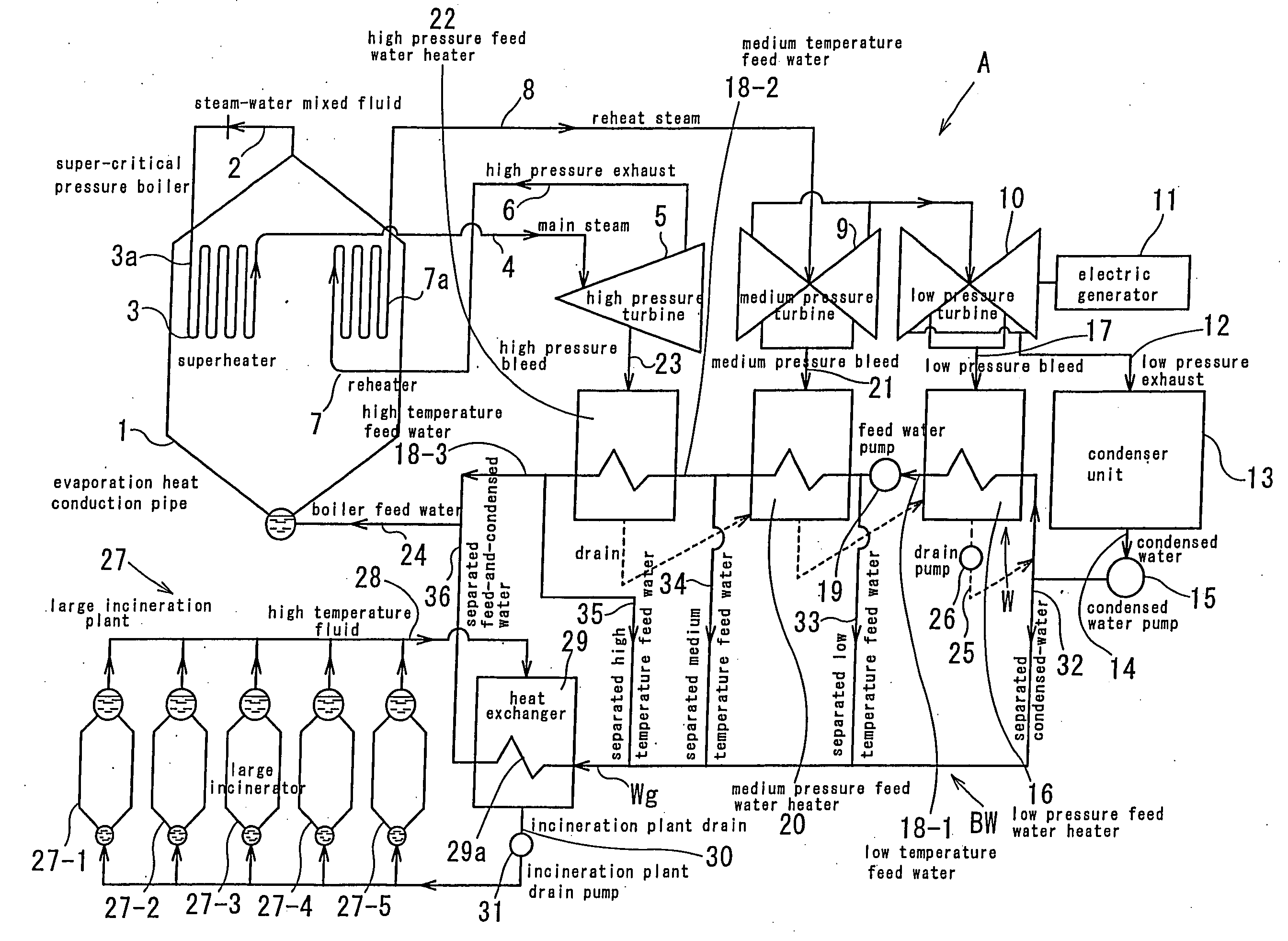
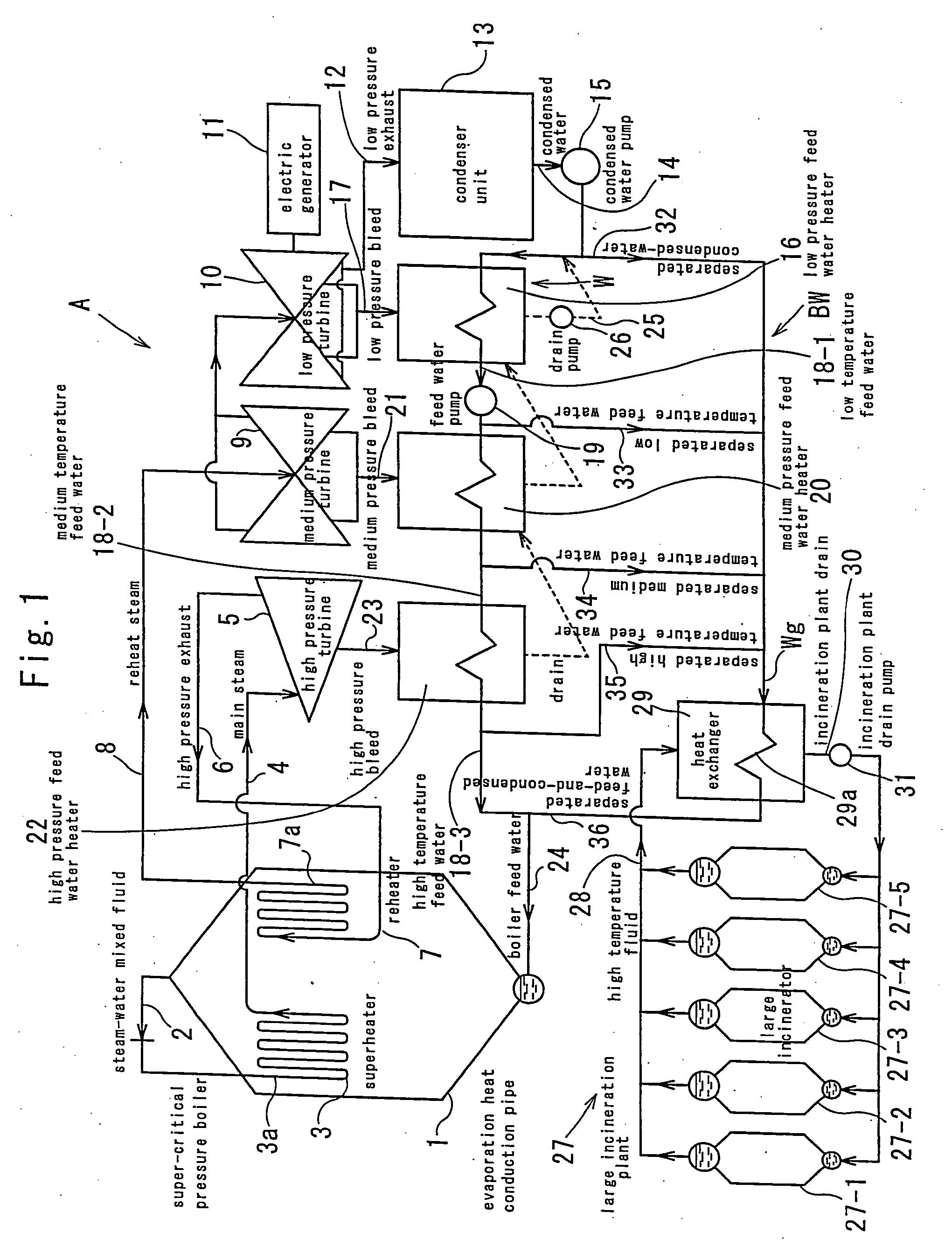
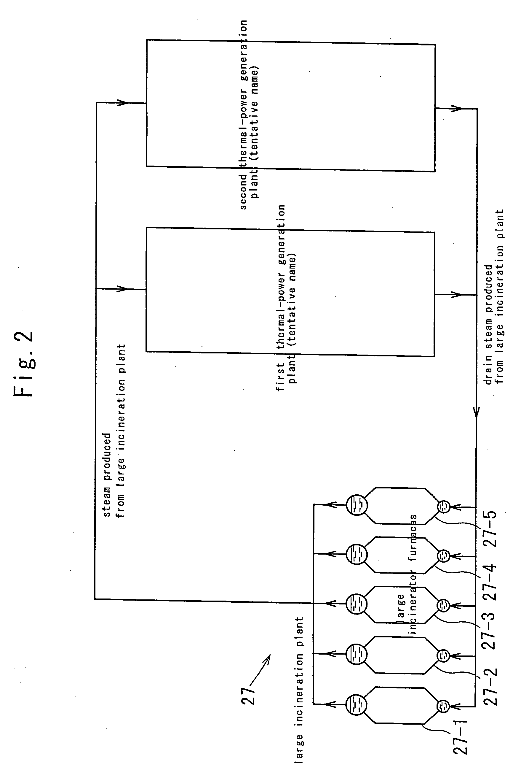
[0078] Referring to FIGS. 1 and 2 which shows a thermal power plant (A) using a reheating-and-regenerating Rankine cycle according to an embodiment of the invention, as shown in FIG. 1, the thermal power plant (A) has the super-critically high pressure boiler 1, the electric generator 11, the condenser unit 13, a feed water path (W) and a feed water bypass (BW). To the feed water bypass (BW), the thermal energy is supplied from five large incinerator furnaces 27-1, . . . , 27-5 installed on a large incineration plant 27. By way of illustration, the thermal power plant (A) is placed at two sites in the large incineration plant 27 as shown in FIG. 2.

[0079] The super-critically high pressure boiler 1 has a superheat conduction pipe 3a at a superheater 3 to produce the main steam 4 with high pressure and high temperature so as to supply it to the high pre...


PUM


Abstract

A reheat-and-regenerating type thermal power plant (A) using Rankine cycle has a water feed bypass (BW) which suppies high temperature fluid (28) produced in a large incineration plant (27) to a heat exchanger (29) and by which confluent feed water (Wg) resulting from the confluence of separated condensed-water (32), separated low temperature feed water (33), separated medium temperature feed water (34) and separated high temperature feed water (35) is supplied to a superheat conduction pipe (3a) through a heat exchanger conduction pipe (29a). The water feed bypass (BW) is installed separately from a feed water path (W), thus insuring an efficient use of the high temperature fluid (28) produced upon incinerating a huge amount of combustible wastes in the large incineration plant (27).

Description

FIELD OF THE INVENTION [0001] The invention relates to a reheating-and-regenerating type thermal power plant using Rankine cycle to make better use of a high temperature fluid (e.g., hot water and steam) produced when a large quantity of combustible wastes are incinerated at a large incineration plant. BACKGROUND OF THE INVENTION [0002] Working steam produced upon incinerating the combustible wastes is mainly employed to a thermal power plant installed in an incineration plant. The thermal power plant, however, comes to a small-scaled facility which reduces a thermic efficiency gained upon converting a heat generation to an electricity. This makes it difficult to produce a thermal power plant to such a degree as applicable to a commercial and business usage. [0003] For the thermal power plant installed in the incineration plant to generate the electricity due to the steam produced when the combustible wastes are incinerated, it is difficult to efficiently use the heat energy produce...

Claims


Application Information

Patent Timeline
Patent Type & Authority Applications(United States)
IPC IPC(8): F02G3/00F01K27/02F01K3/24F01K7/40F22B1/18F22D1/32
CPCF01K3/247Y02E20/16Y02E20/12F01K7/40Y02P80/15
Inventor YAMADA, KATSUSHIGE
Owner OGAWA KIICHIRO
Why Eureka
Try Eureka