Radiator and heatsink apparatus having the radiator

a technology of radiator and heatsink, which is applied in the direction of lighting and heating apparatus, semiconductor/solid-state device details, and domestic stoves or ranges. it can solve the problems of reducing the efficiency of heat dissipation, affecting the cooling performance, and limiting the use of space for heat dissipation, so as to reduce improve cooling performance. , the effect of reducing the size of the heatsink apparatus

Inactive Publication Date: 2006-11-16
PANASONIC CORP
View PDF6 Cites 53 Cited by
  • Summary
  • Abstract
  • Description
  • Claims
  • Application Information

AI Technical Summary

Benefits of technology

[0018] The present invention is provided to overcome the above-identified conventional problems. A purpose of the present invention is to improve cooling performance, to reduce a size of a heatsink apparatus and to effectively use a space for heat dissipation.

Problems solved by technology

However, since the heat-dissipating tubes, which provide channels for the coolant, are processed by extrusion, the channels can only have a straight line shape.
When a space for heat dissipation inside an electronic device is complicated, for example, it is difficult to efficiently fit the heatsink apparatus into the space.
Further, the heat-dissipating tubes cannot have a concave-convex shape on its internal wall, thus hampering improvement in heat dissipation efficiency by using turbulence of the coolant.
Further, since the flexible sheets per se have no definite shape, it is difficult to ensure an air channel when, for example, a plurality of flexible sheets are arranged in layers so as to blow air through gaps formed therebetween.
It is therefore not suitable for improving the heat dissipation performance.

Method used


Image

  • Radiator and heatsink apparatus having the radiator
  • Radiator and heatsink apparatus having the radiator
  • Radiator and heatsink apparatus having the radiator

Examples


first embodiment

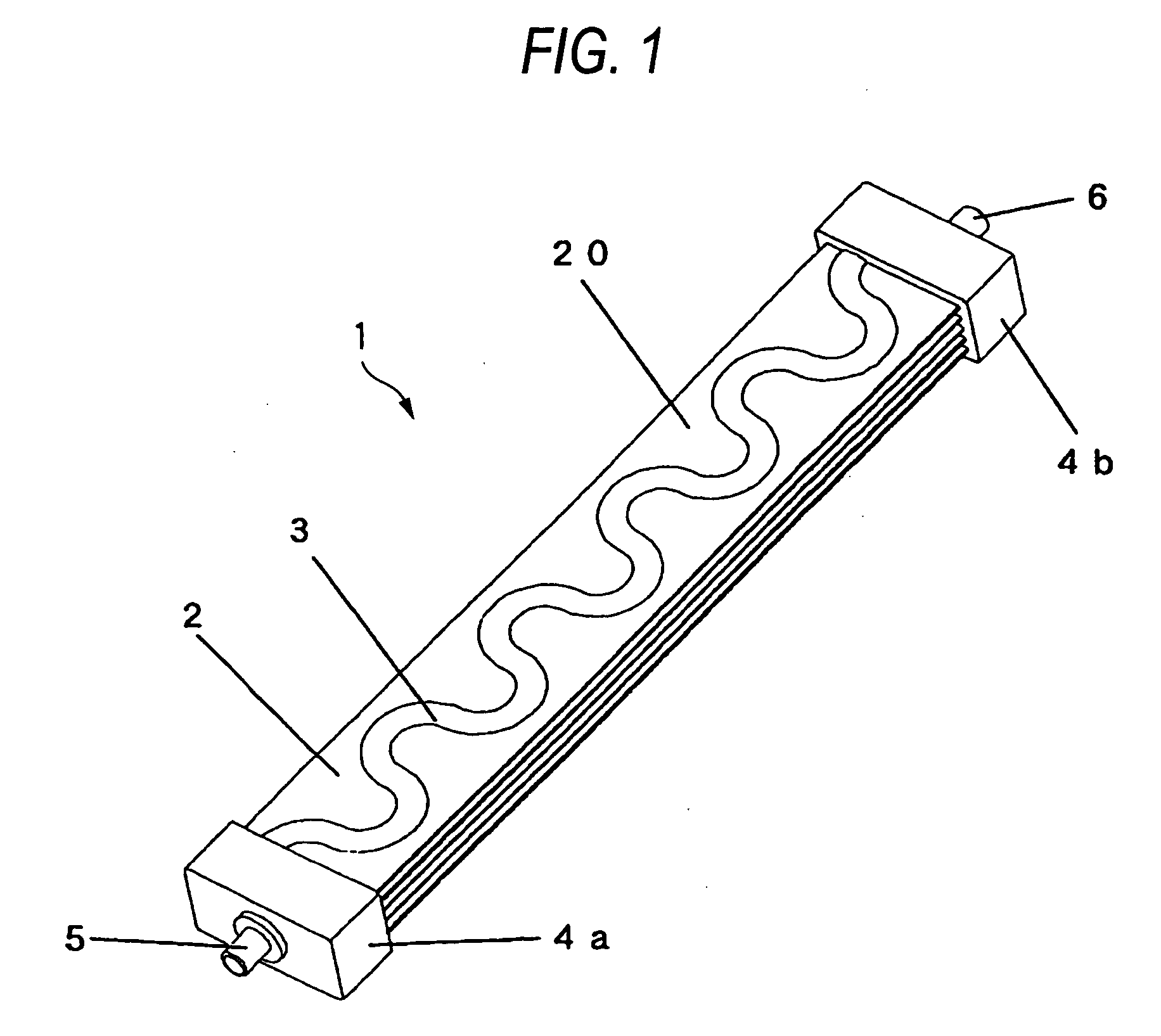
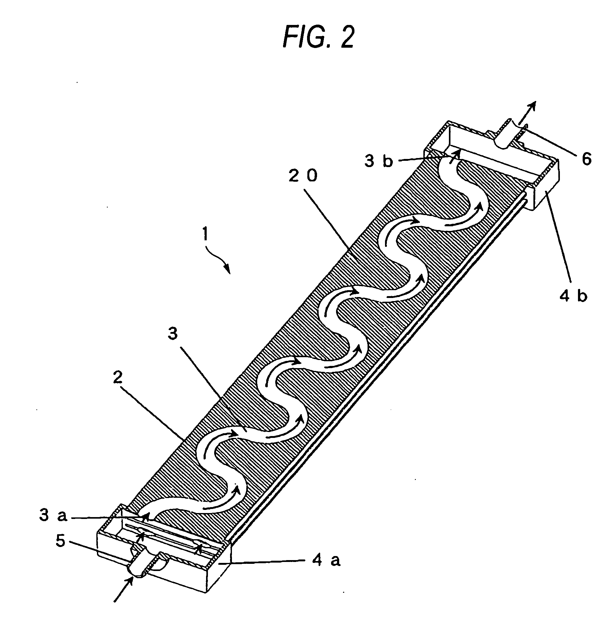
[0038]FIG. 1 is a perspective view of a radiator according to a first embodiment of the present invention. FIG. 2 is a perspective cross-sectional view of the radiator according to the embodiment. FIG. 3 is an exploded view of a flat tube of the radiator according to the embodiment. FIG. 4 is an exploded view of a flat tube having a different shape according to the embodiment. FIG. 5 (a), (b) are perspective views of a complete heat-dissipating part installed with the radiator according to the embodiment. FIG. 6 (a) is a plain view of the uncovered complete heat-dissipating part installed with the radiator according to the embodiment. FIG. 6 (b) is a cross-sectional view along line AA of FIG. 6 (a). FIG. 16 illustrates a heatsink apparatus installed with the complete heat-dissipating part according to the embodiment.

[0039] As shown in FIG. 1, flat tube 2 is formed by bonding two flat metal plates having good thermal conductivity and a definite shape. On a flat metal plate, channel ...

second embodiment

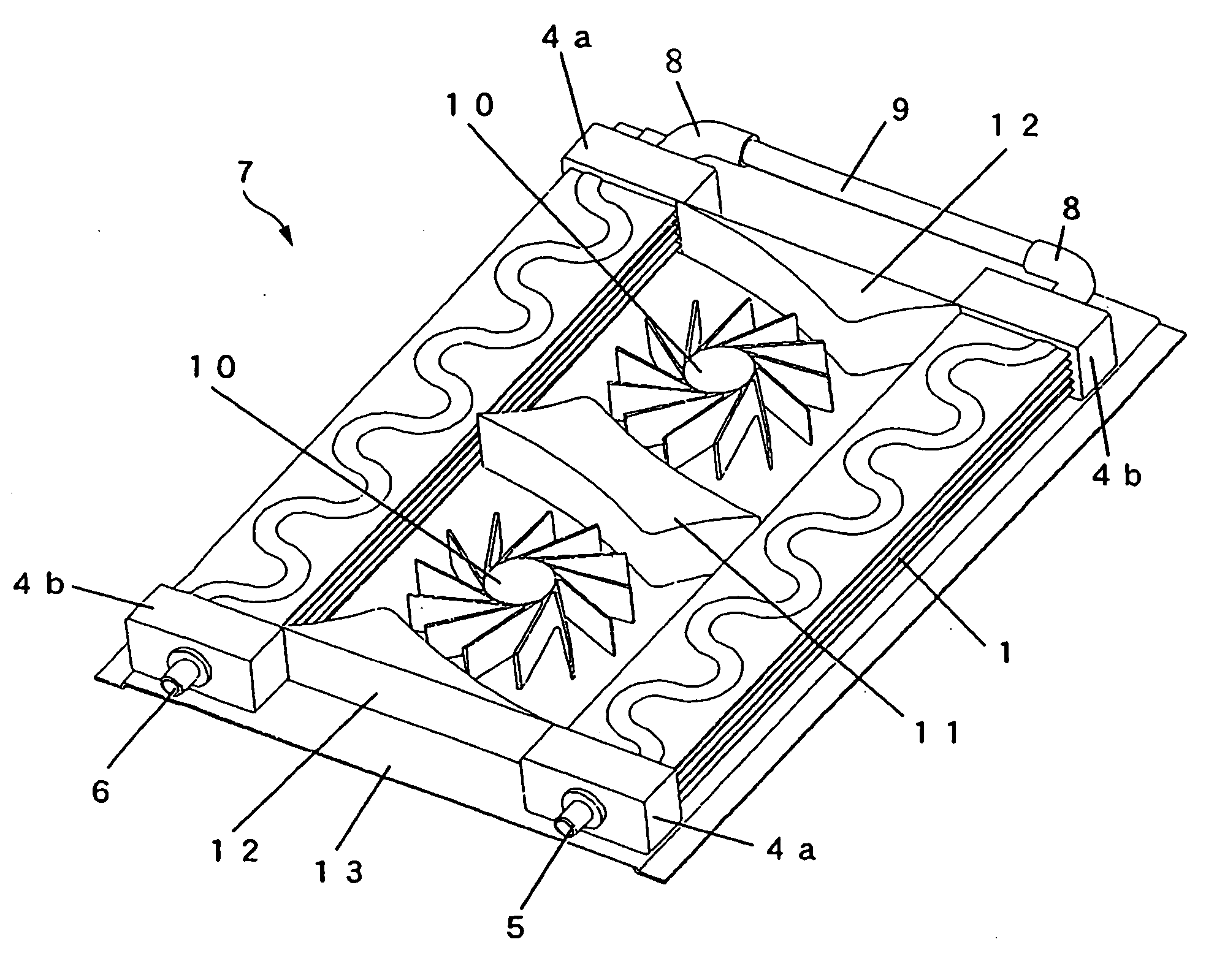
[0061]FIG. 7 is a perspective view of a radiator according to a second embodiment of the present invention. Components same as in the first embodiment are provided with same reference numbers and detailed descriptions thereof are omitted.

[0062] As shown in FIG. 7, a plurality of flat tubes 2 are stacked in layers having a predetermined distance therebetween. Each of flat tubes 2 is provided with a plurality of channels 3 for coolant circulation and planar portion 20 for heat dissipation. To both ends of flat tubes 2 stacked in layers, hollow inlet header 4a and outlet header 4b are connected. Inlet header 4a is provided with inlet 5 for a coolant to enter and outlet header 4b with outlet 6 for the coolant to discharge.

[0063] Inlet 5 and channels 3 are connected via a hollow portion of inlet header 4a. Outlet 6 and channels 3 are connected via a hollow portion of outlet header 4b.

[0064] Flat tube 2 is provided with two serpentine channels 3 having a same shape, which double fluid ...

third embodiment

[0065]FIG. 8 is a plain view of an uncovered complete heat-dissipating part installed with a radiator according to a third embodiment of the present invention. Components same as in the first embodiment are provided with same reference numbers and detailed descriptions thereof are omitted.

[0066] A plurality of flat tubes 2 having an L-shape and being provided with channels 3 and planar portions 20 for heat dissipation are stacked in layers having a predetermined distance therebetween. To both ends of flat tubes 2 stacked in layers, hollow inlet header 4a and outlet header 4b are connected. Inlet header 4a is provided with inlet 5 for a coolant to enter and outlet header 4b with outlet 6 for the coolant to discharge.

[0067] Inlet 5 and channels 3 are connected via a hollow portion of inlet header 4a. Outlet 6 and channels 3 are connected via a hollow portion of outlet header 4b.

[0068] Inlet header 4a and outlet header 4b are disposed at an angle of 90 degrees.

[0069] At an opposite...


PUM


Abstract

A radiator includes: an inlet header having a hollow shape and being provided with an inlet for the coolant to enter; a plurality of flat tubes connecting to the inlet header on one end; and an outlet header having a hollow shape and being provided with an outlet for the coolant to discharge, the outlet header connecting to another end of the plurality of flat tubes. The plurality of flat tubes form channels for the coolant and connect the inlet header and the outlet header.

Description

BACKGROUND OF THE INVENTION [0001] 1. Field of the Invention [0002] The present invention relates to a radiator, which is employed in a liquid cooling system or the like that uses a pump to forcibly circulate a coolant, and a heatsink apparatus having the radiator. [0003] 2. Description of Related Art [0004] Recent computers have shown extremely rapid improvement in data processing speed and thus CPUs operate at clock frequencies significantly higher than in the past. [0005] Heat generated from the CPUs has increased accordingly. Therefore, in addition to a conventional heat dissipation method, in which a heat-dissipating portion, such as a heatsink or heat-dissipating fins, contacts a heat-generating portion, it is indispensable to employ other cooling methods, including: directly cooling the heatsink using a fan; air cooling a heat-dissipating portion in a heatsink module, in which a heat pipe thermally connects a heat-receiving portion to the heat-dissipating portion, using a fan...

Claims


Application Information

Patent Timeline
Patent Type & Authority Applications(United States)
IPC IPC(8): H05K7/20
CPCF28D1/0316F28D1/035F28D1/0358F28D2021/0031F28F9/262H01L2924/0002H01L23/473F28F2250/08H01L2924/00
Inventor NARAKINO, SHIGERUUTSUNOMIYA, WATARUHATANAKA, YOUICHI
Owner PANASONIC CORP
Why Eureka
Try Eureka