Energy collection and power reduction in laser coupling process

a laser coupling and laser technology, applied in the field of apparatus, can solve the problems of high-precision attachments with high thermal expansion, low cost of epoxy attachments, and inability to meet the requirements of high-precision attachments, and achieve the effect of reducing the amount of power used

Inactive Publication Date: 2006-11-16
PANASONIC HEALTHCARE HLDG CO LTD
View PDF30 Cites 1 Cited by
  • Summary
  • Abstract
  • Description
  • Claims
  • Application Information

AI Technical Summary

Benefits of technology

[0004] To reduce the amount of laser power required during the laser coupling process, it may be desirable to use the lost or wasted energy reflected by the solder preform to help heat the solder preform. For this reduction in laser power, a simple, inexpensive apparatus is needed.
[0007] The present invention is also embodied in a method for reducing the amount of power used by a laser for coupling a plurality of components. The exemplary method includes placing a device attaching element on a surface and placing an energy collector proximate to the device attaching element. The energy from a laser beam that is reflected off of the device attaching element is collected by the energy collector. The method creates sufficient coupling between the energy collector and the surface to provide a thermally conductive pathway for the energy between the energy collector and the device attaching element. The method then uses the collected energy of the laser beam to assist in modifying the device attaching element.

Problems solved by technology

Epoxy attachment is low cost but may have too much thermal expansion for high precision attachments.
Furthermore, it may not be reliable over a long period of time due to outgassing and alignment shifts arising from aging and temperature cycling.
Laser weld techniques are reliable but use costly ferrulization of the fiber and specially designed mounts or clips to allow weld attachment of the ferrulized fiber.
The mounts and clips tend to be relatively large, and may creep over time.
Laser soldering techniques however, require relatively high amounts of laser power.
A significant amount of the laser's power may be lost or wasted due to the highly reflective nature of the solder surface.
The large amount of power used by the laser in a typical laser coupling process makes such a process relatively expensive compared, for example, with an epoxy coupling process.
These low cost energy sources however, do not enable specific target soldering within a small space without affecting the surrounding area.
The additional equipment may also add complexity to the system.
Further, the additional equipment may be expensive.

Method used


Image

  • Energy collection and power reduction in laser coupling process
  • Energy collection and power reduction in laser coupling process
  • Energy collection and power reduction in laser coupling process

Examples


Embodiment Construction

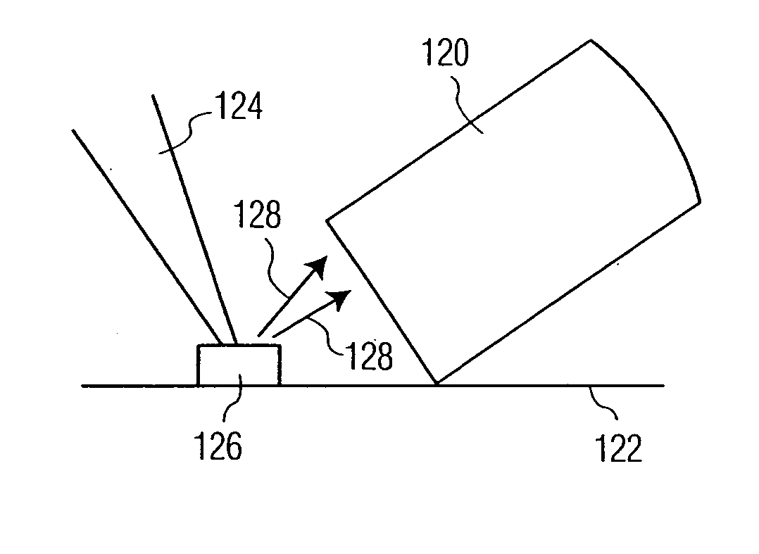
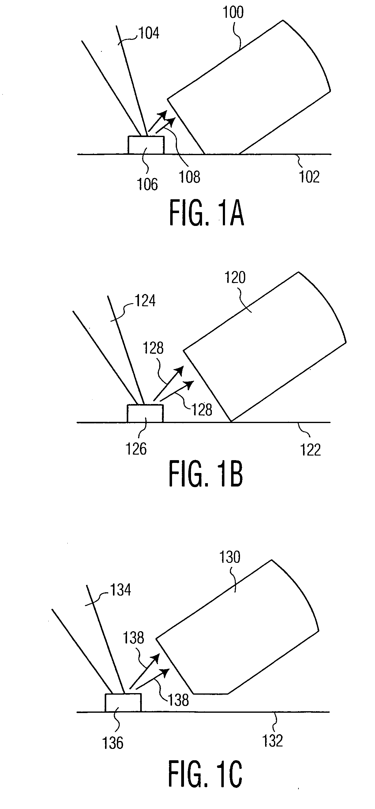
[0019]FIG. 1A shows an exemplary embodiment of the invention. As shown, laser beam 104 irradiates device attaching element 106 which is located on surface 102. Laser energy 108 is reflected from device attaching element 106 in different directions. Energy collector tip 100 is proximate to device attaching element 106 so that at least a portion of the laser energy 108 is collected by energy collector tip 100. Energy collector tip 100 is also in contact with surface 102. The precise location of energy collector tip 100 and the area of collector tip 100 that is in contact with surface 102 shown in FIG. 1 is merely illustrative and is not limiting.

[0020] It is contemplated that the device attaching element may be made of a number of different materials used during a laser coupling process, which have the desired thermal and mechanical properties. It is noted that the desired thermal and mechanical properties may vary depending on the type of components which are being coupled. These ma...


PUM

PropertyMeasurementUnit
wavelengthaaaaaaaaaa
poweraaaaaaaaaa
wavelengthsaaaaaaaaaa

Abstract

An energy collector is used to assist a laser coupling process by reducing the amount of output power of a laser that is used to modify a device attaching element. The energy collector includes an energy collector tip configured to be placed proximate to a device attaching element during the laser coupling process. The energy collector tip is configured to receive laser energy reflected from the device attaching element during the laser coupling process and is formed from a material that converts this reflected energy to heat. Sufficient thermal coupling is created between the energy collector and a surface to provide a conductive pathway for the energy, which has been converted to heat, between the energy collector and the device attaching element.

Description

FIELD OF THE INVENTION [0001] The present invention relates generally to an apparatus for assisting in a laser coupling process by reducing the required amount of laser power, and, in particular, to an apparatus for collecting laser energy reflected from a device attaching element and converting the laser energy to heat during the laser coupling and fiber attach process. BACKGROUND OF THE INVENTION [0002] Laser soldering for attaching multiple components may be used in a variety of systems, including optical systems, electronic systems and micro-mechanical systems, including micro-electro-mechanical systems (MEMS) and micro-opto-electro-mechanical systems (MOEMS). For example, laser soldering may be used to securely position an optical fiber to couple the optical output from a laser diode into the optical fiber during the construction of laser transmitters. Typically, fiber-coupled diode lasers are packaged in metal butterfly packages, which may be gold plated. The fiber is held in ...

Claims


Application Information

Patent Timeline
Patent Type & Authority Applications(United States)
IPC IPC(8): B23K26/20
CPCB23K26/422B23K1/0056B23K26/702
Inventor OHARA, TETSUO
Owner PANASONIC HEALTHCARE HLDG CO LTD
Why Eureka
Try Eureka