Front illuminated back side contact thin wafer detectors

a detector and front-side contact technology, applied in the field of radiation detectors, can solve the problems of adversely affecting the performance of detectors, transistors and integrated circuits, and detectors showing an increased reverse-bias current, and achieve the effects of reducing radiation damage susceptibility, reducing cross-talk effects, and increasing flexibility in application

Inactive Publication Date: 2006-11-16
OSI OPTOELECTRONICS
View PDF48 Cites 55 Cited by
  • Summary
  • Abstract
  • Description
  • Claims
  • Application Information

AI Technical Summary

Benefits of technology

[0011] The present invention is directed toward a detector structure, detector arrays, a method of detecting incident radiation, and a method of manufacturing the detectors. The present invention comprises several embodiments that provide for reduced radiation damage susceptibility, decreased affects of cross-talk, and increased flexibility in application. The present invention comprises a plurality of front side illuminated photodiodes, optionally organized in the form of an array, with both the anode and cathode contact pads on the back side. The front side illuminated, back side contact (FSL-BSC) photodiodes have superior performance characteristics, including less radiation damage, less crosstalk using a suction diode, and reliance on reasonably thin wafers. Another advantage of FSL-BSC photodiodes of the present invention is that high density with high bandwidth applications can be effectuated.

Problems solved by technology

One problem with detection devices is that they are susceptible to various radiation damage mechanisms, such as displacement damage resulting in total dose effects and ionization damage resulting in bulk effects.
Both mechanisms adversely affect the performance of detectors, transistors and integrated circuits.
Over time, detectors show an increased reverse-bias current and increased forward voltage drop due to radiation damage.
Further, a change in doping level, due to radiation damage, adversely affects the width of the depletion region, i.e. the voltage required for full depletion and a decrease in carrier lifetime results in signal loss as carriers recombine while traversing the depletion region.
Another disadvantage with conventional detection devices is the amount and extent of crosstalk that occurs between adjacent detector structures, primarily as a result of minority carrier leakage current between diodes.
However, at conventional doping levels utilized for diode arrays of this type, the diffusion length of minority carriers generated by photon interaction in the semiconductor is in the range of at least many tens of microns, and such minority carriers have the potential to affect signals at diodes away from the region at which the minority carriers were generated.
Therefore, the spatial resolution obtainable may be limited by diffusion of the carriers within the semiconductor itself, even if other components of the optical system are optimized and scattered light is reduced.
Additionally, conventional front surface contact photodiodes require greater space devoted to electrical contacts and, therefore, limit the density of photodiodes in a given application.
However, these disclosures fail to provide sufficient teachings to inform one of ordinary skill in the art how to manufacture such modified top-surface photodiode arrays.

Method used


Image

  • Front illuminated back side contact thin wafer detectors
  • Front illuminated back side contact thin wafer detectors
  • Front illuminated back side contact thin wafer detectors

Examples


Embodiment Construction

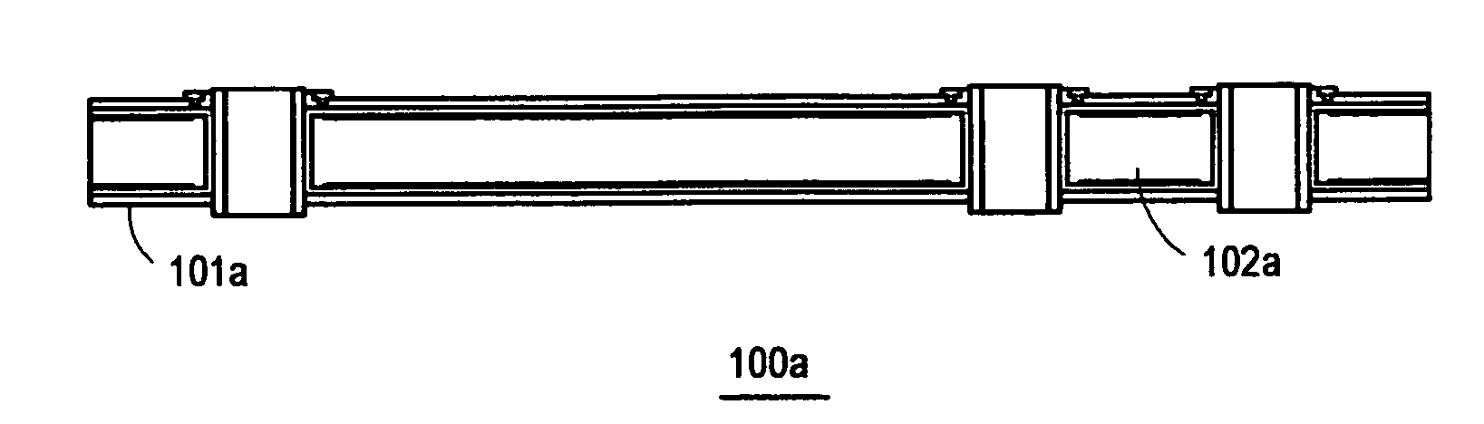
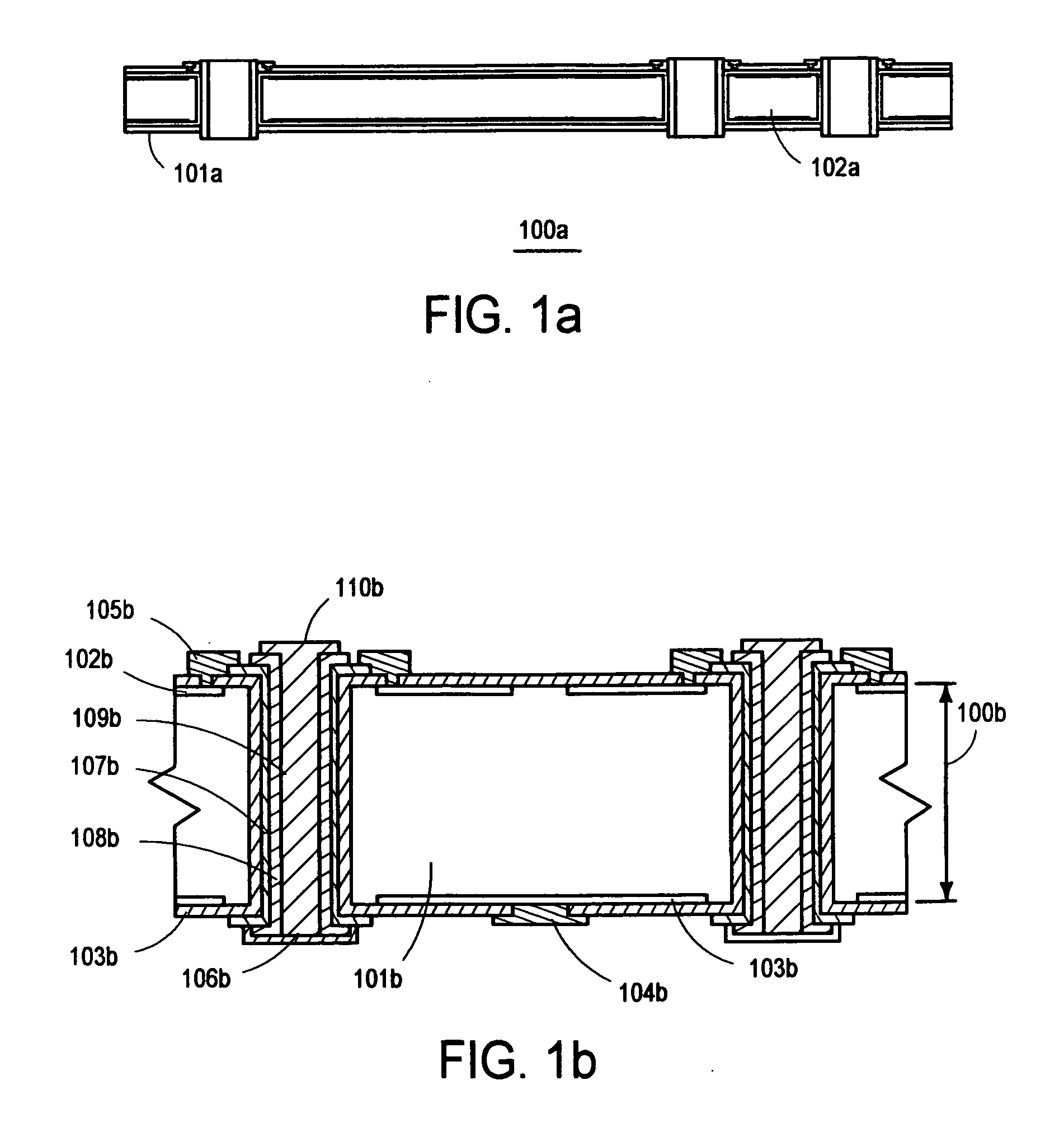
[0037] The present invention is directed toward a detector structure, detector arrays, a method of detecting incident radiation, and a method of manufacturing the detectors. The present invention comprises several embodiments that provide for reduced radiation damage susceptibility, decreased affects of cross-talk, and increased flexibility in application. Various modifications to the disclosed embodiments will be readily apparent to those of ordinary skill in the art, and the disclosure set forth herein may be applicable to other embodiments and applications without departing from the spirit and scope of the present invention and the claims hereto appended. Thus, the present invention is not intended to be limited to the embodiments described, but is to be accorded the broadest scope consistent with the disclosure set forth herein.

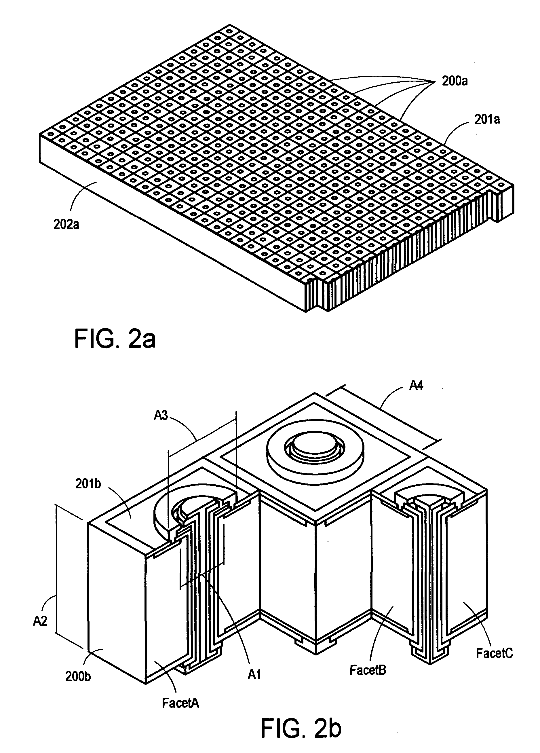
[0038] In one embodiment, the present invention comprises a plurality of front side illuminated photodiodes, optionally organized in the form of an arra...


PUM


Abstract

The present invention is directed toward a detector structure, detector arrays, a method of detecting incident radiation, and a method of manufacturing the detectors. The present invention comprises several embodiments that provide for reduced radiation damage susceptibility, decreased affects of cross-talk, and increased flexibility in application. In one embodiment, the present invention comprises a plurality of front side illuminated photodiodes, optionally organized in the form of an array, with both the anode and cathode contact pads on the back side. The front side illuminated, back side contact photodiodes have superior performance characteristics, including less radiation damage, less crosstalk using a suction diode, and reliance on reasonably thin wafers. Another advantage of the photodiodes of the present invention is that high density with high bandwidth applications can be effectuated.

Description

CROSS REFERENCE TO RELATED APPLICATIONS [0001] This invention is a continuation of U.S. patent application No. 10 / 797,324 filed on Mar. 10, 2004 which relies on, for priority, U.S. Provisional Application 60 / 468,181, having a priority date of May 5, 2003, entitled “DETECTORS WITH IMPROVED RADIATION DAMAGE AND CROSSTALK CHARACTERISTICS”.FIELD OF THE INVENTION [0002] The present invention pertains generally to the field of radiation detectors, and in particular, relates to radiation detectors manufactured with thinner wafers, thereby yielding reduced crosstalk between detecting regions and decreased susceptibility to radiation damage, and with contacts extending from a front surface to a back surface, thereby permitting higher photodiode density applications. BACKGROUND OF THE INVENTION [0003] Arrays of photosensitive diodes are used in an assortment of applications including, but not limited to, radiation detection, optical position encoding, and low light-level imaging, such as nigh...

Claims


Application Information

Patent Timeline
Patent Type & Authority Applications(United States)
IPC IPC(8): H01L31/00H01L27/146H01L31/06H01L31/103H01L31/18
CPCH01L27/14601H01L27/14643H01L31/1804H01L31/103H01L27/14689
Inventor BUI, PETER STEVENTANEJA, NARAYAN DASS
Owner OSI OPTOELECTRONICS
Why Eureka
Try Eureka