Voltage controlled current source device

a current source and voltage control technology, applied in the direction of electric variable regulation, process and machine control, instruments, etc., can solve the problems of fast application, achieve high output current, eliminate limitations to voltage headroom or power efficiency, and high accuracy

Active Publication Date: 2006-11-16
TEXAS INSTR INC
View PDF11 Cites 15 Cited by
  • Summary
  • Abstract
  • Description
  • Claims
  • Application Information

AI Technical Summary

Benefits of technology

[0006] As the reference current is mirrored to the load in a feed-forward arrangement, in particular via a dynamically matched current mirror, there is no need for a current control loop with a shunt resistor and an instrumentation amplifier (INA). In particular, a dynamic element matching approach employed in the current mirror ensures high accuracy throughout a large range of the output current. Limitations to the voltage headroom or power efficiency at high output currents are eliminated. Although the driver which determines the current forced through the current set resistor preferably includes an operational amplifier which is part of a closed control loop, the feedback loop is short, which leads to a fast application. Typically, no additional (external) compensation is required for that loop.

Problems solved by technology

Although the driver which determines the current forced through the current set resistor preferably includes an operational amplifier which is part of a closed control loop, the feedback loop is short, which leads to a fast application.

Method used


Image

  • Voltage controlled current source device
  • Voltage controlled current source device
  • Voltage controlled current source device

Examples


Embodiment Construction

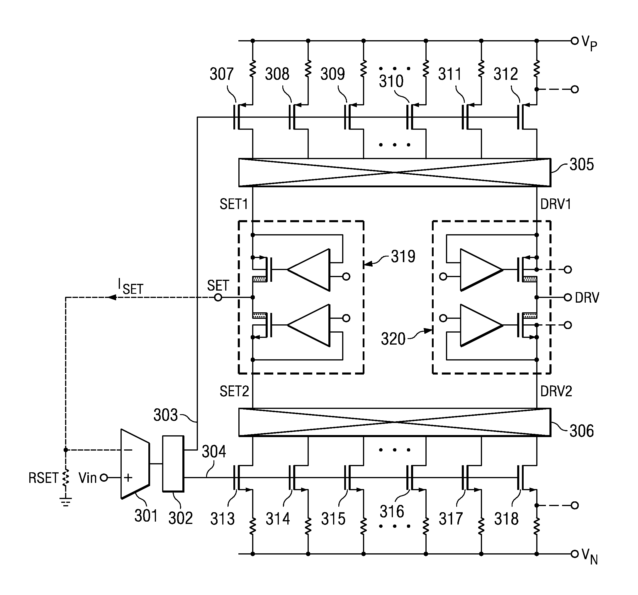
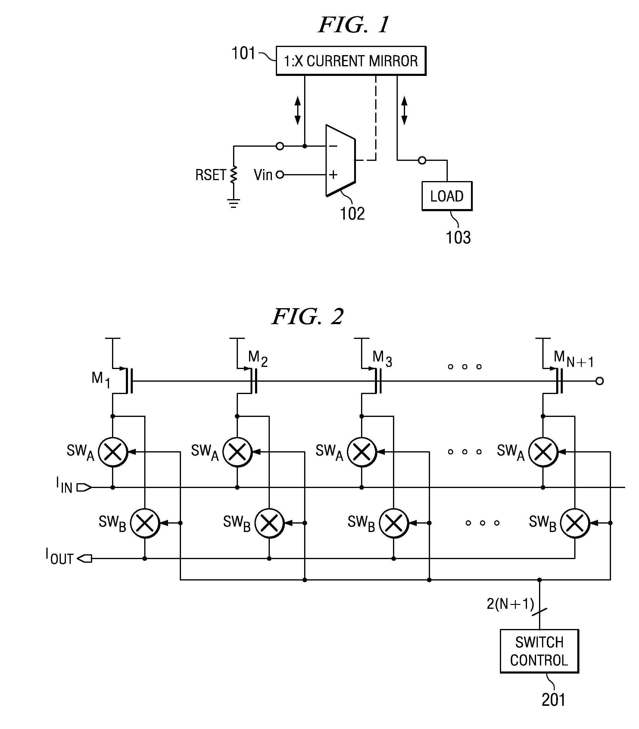
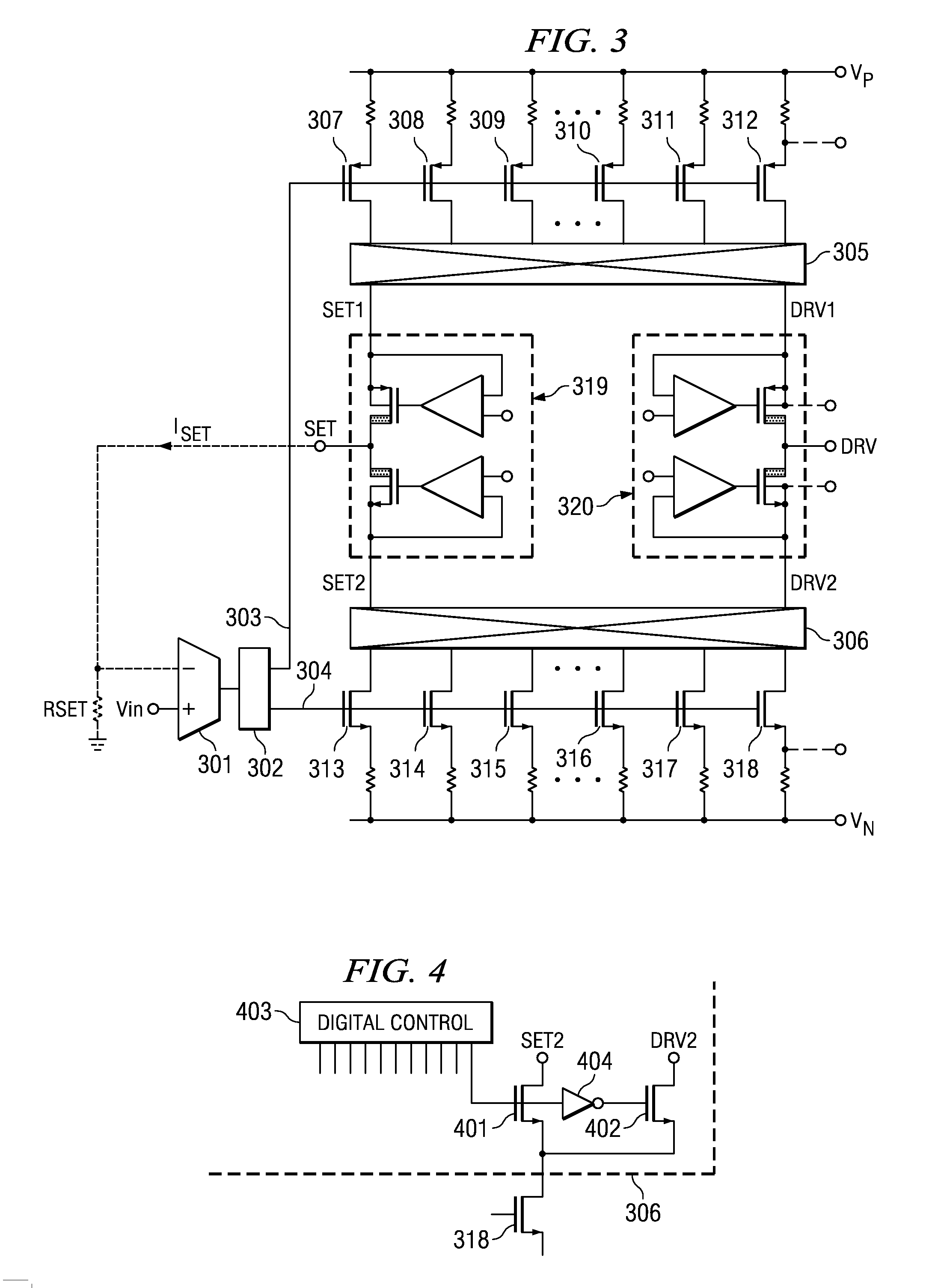
[0019] With reference to FIG. 1, an example integrated circuit implementation of a voltage controlled current source device comprises a current set resistor RSET, a current mirror block 101, a driver including an operational amplifier 102 with a negative and a positive input and an output. The current set resistor RSET may be off-chip or on-chip as part of the integrated circuit. The current set resistor RSET is connected across the negative input of the amplifier 102 and ground GND or, as an alternative, another reference voltage instead of ground GND. A control voltage Vin is applied to the positive input of the amplifier 102. The current mirror block 101 has a first output connected to the negative input of the amplifier 102 and a second output connected to a load 103. The output of the amplifier 102 provides a gate control voltage to the current mirror block 101.

[0020] The current mirror block 101 comprises multiple current sources, all having the same gate bias supplied by the...


PUM


Abstract

An integrated voltage controlled current source device is provided, that extends the high accuracy, low drift output current over a large current range, and provides more headroom and better power efficiency than the standard shunt resistor and INA (instrumentation amplifier) current source arrangement. The device has a control voltage input, a load current output and a current set terminal for a connection of a current set resistor. It contains a selected leg biasing set voltage, corresponding to a control voltage applied to the control voltage input of a regulating driver amplifier providing a regulated voltage to be applied across the current set resistor, thereby causing a reference current to flow through the current set resistor and selected leg(s) of a current mirror. Furthermore, the device contains a dynamically matched current mirror that mirrors the reference current to the load output current. The algorithm for selecting the current mirror legs may be a pseudo-random or a defined pattern.

Description

FIELD OF THE INVENTION [0001] The invention relates to a voltage controlled current source device, in particular with an integrated circuit. BACKGROUND OF THE INVENTION [0002] Voltage controlled current source applications typically use a shunt resistor in series with the output load to sense the load current. The load current is fed to an instrumentation amplifier (INA) to measure the voltage drop across the shunt resistor and to feed it back to the input, thereby closing the control loop. [0003] With this approach, which is widely used, to achieve good accuracy both the (shunt) resistor and the INA must have high accuracy and low drift. This leads to additional cost and board space. Furthermore, the voltage drop across the shunt resistor reduces the voltage headroom to the load and the power efficiency. In addition, the range of the current for an accurate output is limited. For small current levels through the shunt resistor, errors of the INA dominate; whereas, for large current...

Claims


Application Information

Patent Timeline
Patent Type & Authority Applications(United States)
IPC IPC(8): G05F3/16
CPCG05F3/262
Inventor SCHAFFER, VIOLABURT, RODNEY T.METZGER, JURGEN
Owner TEXAS INSTR INC
Why Eureka
Try Eureka