Method and apparatus for testing RFID devices

a technology of radio frequency identification and test method, which is applied in the direction of burglar alarm mechanical actuation, burglar alarm by hand-portable object removal, instruments, etc., can solve the problems of time and cost associated with the antenna assembly process, and the failure of functional testing of the assembled rfid devi

Inactive Publication Date: 2006-11-16
RUIZHANG TECH LTD CO
View PDF13 Cites 34 Cited by
  • Summary
  • Abstract
  • Description
  • Claims
  • Application Information

AI Technical Summary

Benefits of technology

[0006] A method and apparatus for testing RFID straps is described. In one embodiment, the method includes coupling an array of RFID straps to an RFID tester, mu...

Problems solved by technology

At this point in the manufacturing process, an assembled RFID device may fail functional testing if the antenna connection is poor or if the RFID chip is defective.
If the cau...

Method used


Image

  • Method and apparatus for testing RFID devices
  • Method and apparatus for testing RFID devices
  • Method and apparatus for testing RFID devices

Examples


Embodiment Construction

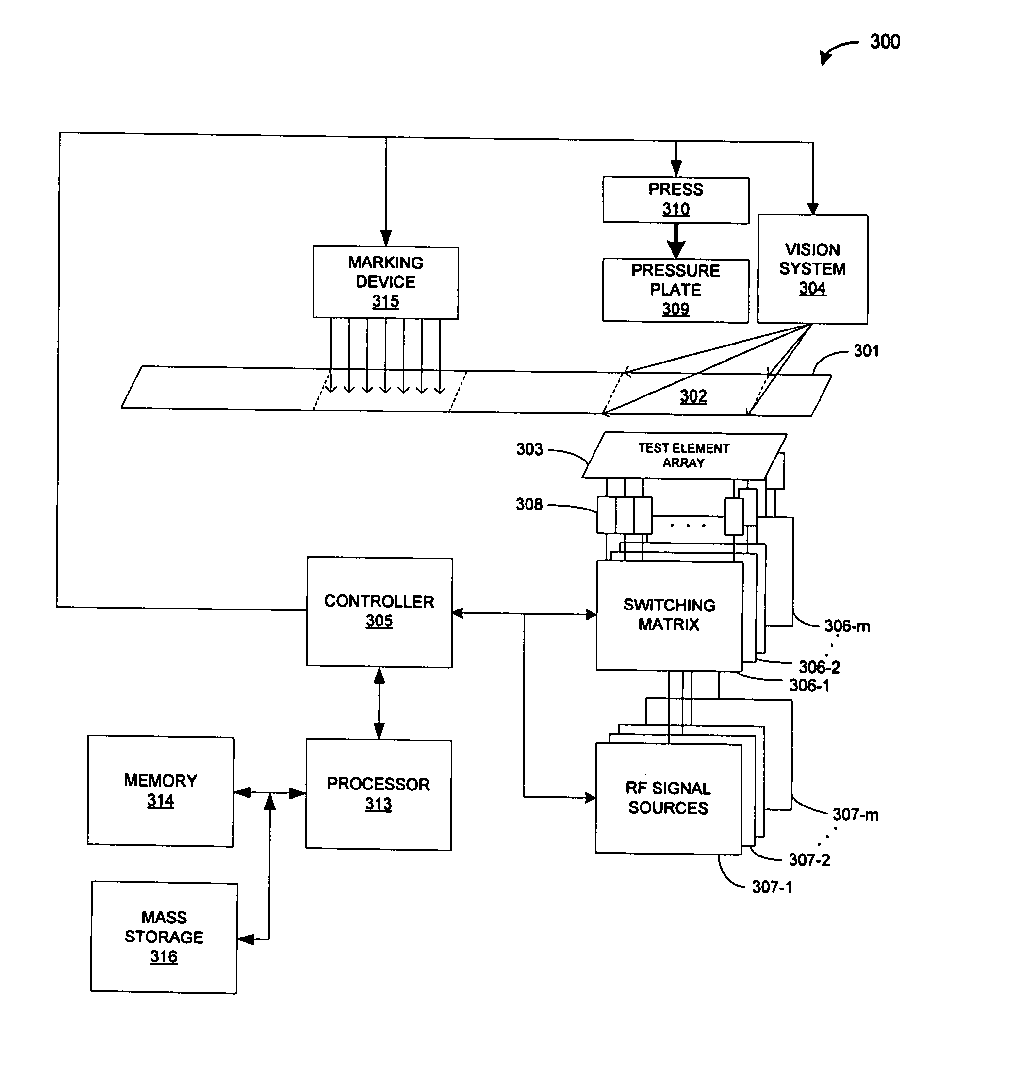
[0031]FIG. 3 illustrates a test system 300 according to one embodiment of the invention. In FIG. 3, a continuous roll of web material 301 contains arrays of RFID straps arranged as frames 302 of m columns and n rows of RFID devices. A system of rollers, guides and motors (not shown) may be used in a conventional manner to transport the web material 301 across an m by n array of test elements 303. As described in detail below, the test element array 303 may be an array of printed elements on a printed circuit card, which may allow the array of RFID straps to be either directly coupled to the array of test elements 303, or capacitively coupled to the array of test elements 303. Alternatively, the array of test elements 303 may be an array of spring-loaded contact pins, in which case the array of RFID straps may be directly coupled to the array of test elements 303.

[0032] Each of the m columns of n test elements in test element array 303 may be connected to one of m switching matrices...


PUM


Abstract

A method and apparatus for testing RFID straps. Arrays of RFID straps in a roll-to-roll process are coupled to an array of test elements. RF programming and interrogation signals are frequency and time multiplexed to the RFID array. Return signals are detected to determine sensitivity and programmability parameters of the RFID straps.

Description

TECHNICAL FIELD [0001] Embodiments of the invention relate to the field of radio frequency identification (RFID) systems and, in particular, to testing RFID devices. BACKGROUND [0002] Radio frequency identification (RFID) devices are used in the form of RFID labels or RFID tags to associate objects with an identification code that may be read or programmed at a distance by stimulating the RFID device with a radio frequency (RF) interrogation or programming signal. Typically, an RFID device consists of an active or passive semiconductor chip assembled with an antenna to receive RF energy from a reader and to transmit or reflect RF energy to the reader in response to an interrogation or programming signal. [0003] High volume manufacturing methods and systems have been developed to produce RFID devices. One system, developed by Alien Technology Corporation of Morgan Hill, Calif., and described in U.S. Pat. No. 6,683,663, utilizes a fluidic self-assembly (FSA) process to deposit RFID ch...

Claims


Application Information

Patent Timeline
IPC IPC(8): G08B13/14
CPCG01R31/2822G06K7/0095G01R31/31926G01R31/31905H01L2924/15153G06K19/07G06K7/00G01R31/319G06K17/00
Inventor CARRENDER, CURTIS LEEHADLEY, MARK A.
Owner RUIZHANG TECH LTD CO
Why Eureka
Try Eureka