
Color filter substrate, method of manufacturing color filter substrate, electro-optical device, and electronic apparatus

a technology of color filter substrate and color filter substrate, which is applied in the field of color filter substrate, method of manufacturing color filter substrate, electrooptical device, and electronic apparatus, can solve the problems of large absorption of display light by color filter substrate, inability to recognize visual structure in pixels of color filter substrate (specifically, the boundary between the first resin and the second resin), and achieves less light absorption, improved reflectance in the reflective region, and higher luminance

Inactive Publication Date: 2006-11-16
SEIKO EPSON CORP
View PDF4 Cites 4 Cited by
  • Summary
  • Abstract
  • Description
  • Claims
  • Application Information

AI Technical Summary

Benefits of technology

[0007] An advantage of the invention is that it provides a color filter substrate that the structure in pixels of a color filter substrate is not easily recognized visually by an observer, a method of manufacturing a color filter substrate, a electro-optical device including the color filter substrate, and an electronic apparatus including the electro-optical device.
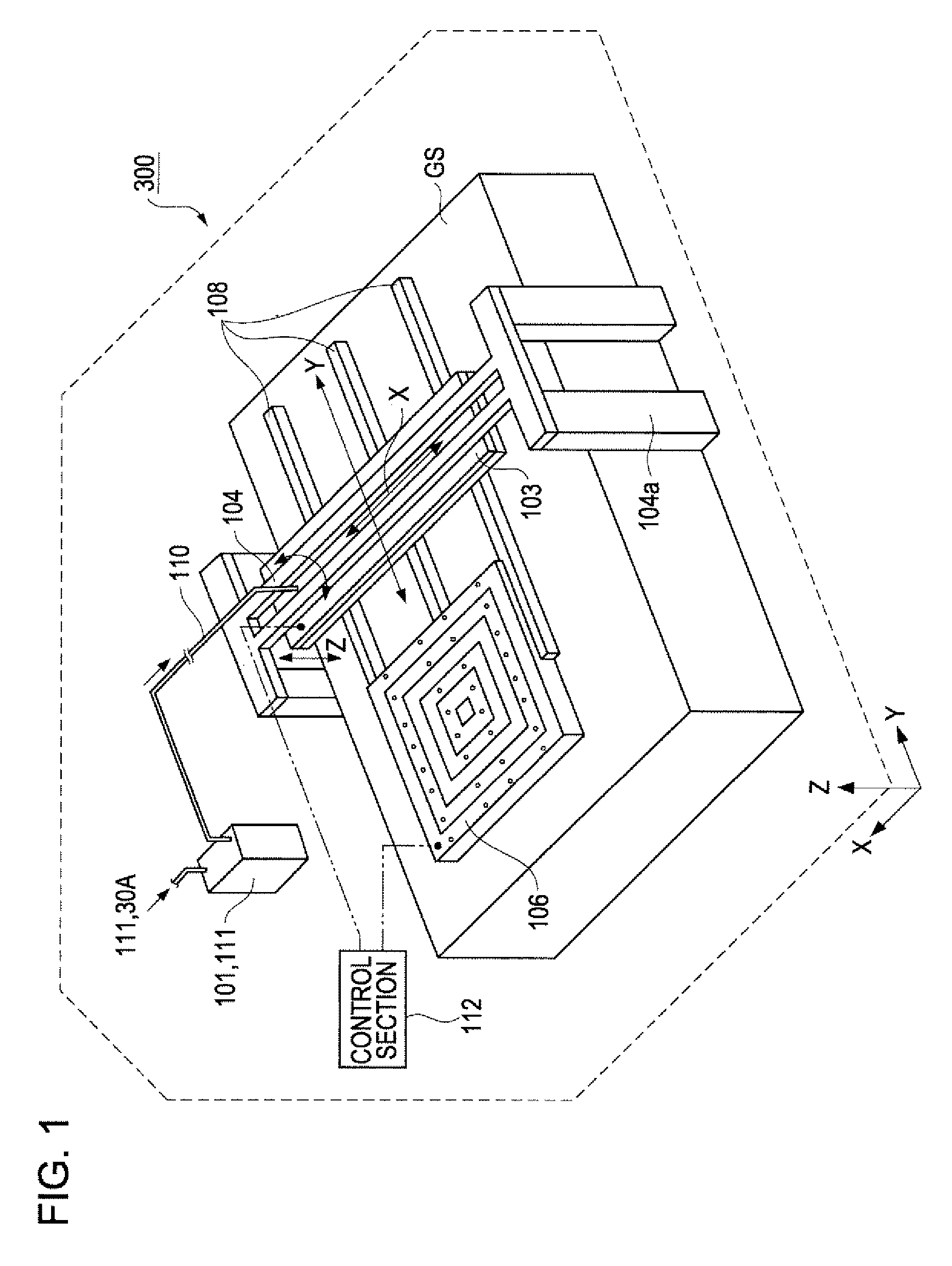
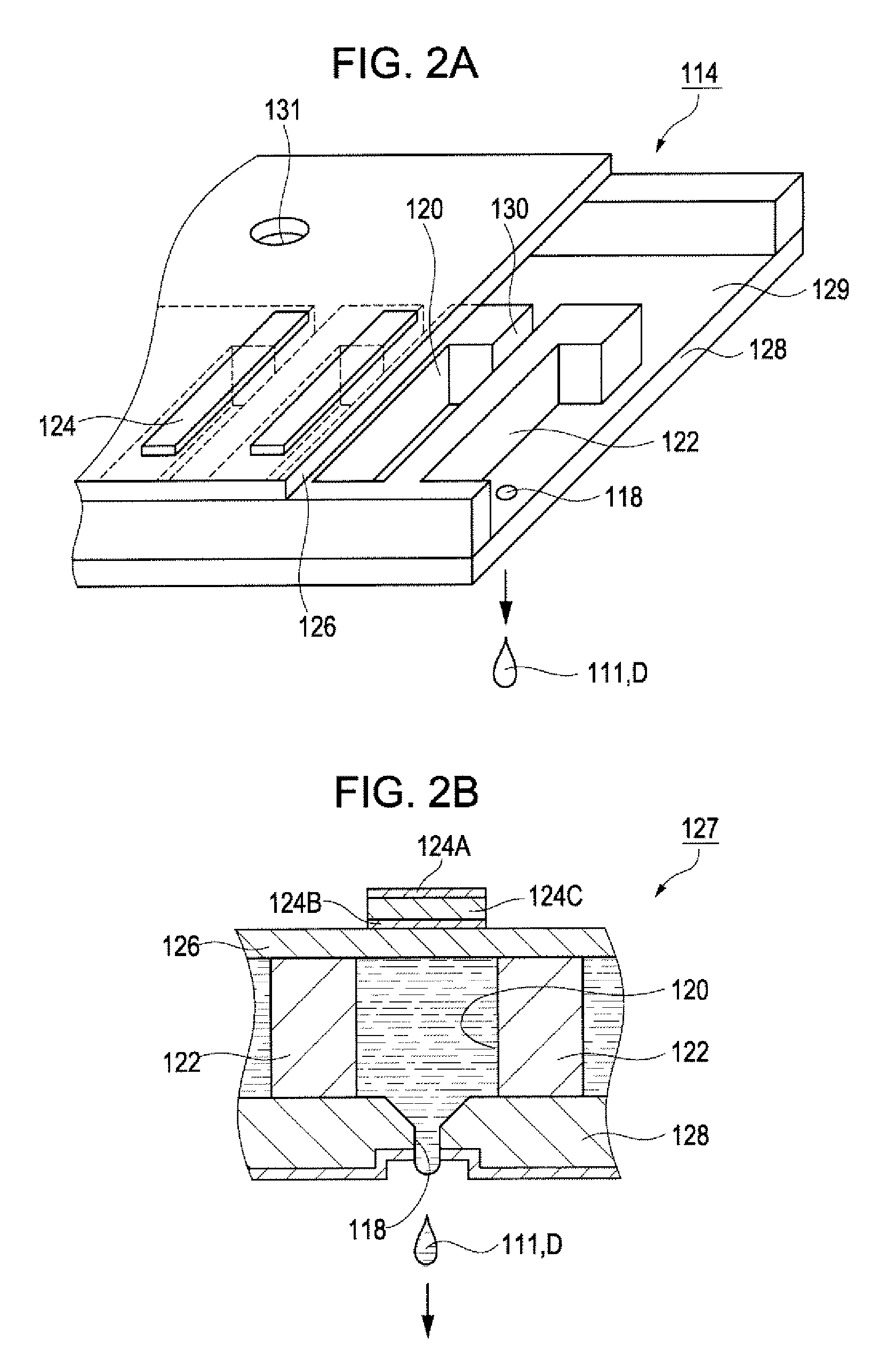
[0008] According to a first aspect of the invention, there is provided a method of manufacturing a color filter substrate including: forming partition walls on a base member, applying a first functional liquid containing a first resin having translucency to a concave part defined by a surface of the base member and side surfaces of the partition walls, using a droplet discharge apparatus, and applying a second functional liquid containing a second resin having translucency and having transmittance different from that of the first resin to the concave part, using a droplet discharge apparatus.
[0009] According to the above method, the first functional liquid and the second functional liquid which have been applied to the concave part are mixed near a boundary therebetween, and thereby the boundary between the first resin and the second resin becomes obscure. Moreover, for example, even in a case where the second functional liquid is applied after the applied first functional liquid has been dried, the first functional liquid is dissolved again by a solvent included in the second functional liquid to cause the above mixing, and thereby the boundary between the first resin and the second resin will be in an obscure state. Therefore, a transmittance changes continuously from a region in which the first resin is disposed to a region in which the second resin having a transmittance different from the first resin is disposed. Therefore, the structure in pixels of a color filter substrate (specifically, a boundary between the first resin and the second resin) is not easily recognized visually by an observer. This effect can also be achieved in any one of a case in which the first functional liquid and the second functional liquid are disposed in different regions in the concave part, a case in which the first functional liquid is disposed in a portion of the concave part and the second functional liquid is disposed in the whole concave part so as to cover the first functional liquid, and a case in which the first functional liquid is disposed in the whole concave part, and the second functional liquid is disposed in a portion of the first functional liquid.
[0010] In the method of manufacturing a color filter substrate, preferably, the first resin is substantially transparent and the second resin contains a pigment and corresponds to one color. At this time, the region in which the first resin is disposed has less absorption of light and higher luminance than the region in which the first resin is not disposed, but only the second resin is disposed. In this way, according to the above method, color filter substrates having different luminances according to regions in the concave part can be manufactured.
[0011] Here, the second functional liquid application may include applying a plurality of the second functional liquids corresponding to different colors to the concave parts which are different from one another. According to this method, a color filter substrate applicable to an electro-optical device capable of performing a color display can be manufactured.
[0012] Moreover, the base member has a reflecting film on a portion of the surface thereof, and the first functional liquid application may include applying the first functional liquid to at least a portion of the region of the concave part in which the reflecting film is disposed. According to this method, in the region (hereinafter referred to as “reflective region”) of the concave part in which the reflecting film is disposed, the first resin which is transparent and the second resin (hereinafter, an element in which a resin containing a pigment is fixed on the base member is also referred to as “coloring element”) containing a pigment coexist, while only a coloring element is disposed in the region (hereinafter referred to as “transmissive region”) in which no reflecting film is disposed. Therefore, the reflectance in the reflective region can be improved, while maintaining the color-developing property of the light that is transmitted through the transmissive region.

Problems solved by technology

Therefore, there is a problem in that the absorption of display light by the color filters is large, and display becomes dark.
Therefore, there is a problem in that an observer might visually recognize these boundaries as lines which should not be naturally displayed at the time of display.
Therefore, the structure in pixels of a color filter substrate (specifically, a boundary between the first resin and the second resin) is not easily recognized visually by an observer.

Method used


Image

  • Color filter substrate, method of manufacturing color filter substrate, electro-optical device, and electronic apparatus
  • Color filter substrate, method of manufacturing color filter substrate, electro-optical device, and electronic apparatus
  • Color filter substrate, method of manufacturing color filter substrate, electro-optical device, and electronic apparatus

Examples


first embodiment

A. Color Filter Substrate

[0040]FIG. 4B is a plan view of a color filter substrate 1 manufactured using a method of manufacturing a color filter substrate according to the invention. The color filter substrate 1 has a base member 10 including a glass substrate 11, and a red coloring element 31R disposed on the base member 10, a green coloring element 31G, and a blue coloring element 31B (refer to FIG. 4A).

[0041] The color filter substrate 1 has a plurality of regions 19 which are vertically and horizontally disposed in a matrix and which are corresponding to pixels, respectively, of a liquid crystal display device 400 (refer to FIG. 14). The drawing in which, while paying attention to one of the regions 19, a portion of the one region is enlarged is FIG. 4A. As can be seen from this drawing, each region 19 includes a large number of red pixels 20R, green pixel 20G, and blue pixel 20B, and these pixels are regularly arranged repeatedly in this order (in the following, the pixels 20...

second embodiment

[0089] In the above first embodiment, in the pixel 20, although the transparent resin 30 and the coloring element 31R (31G, 31B) are disposed in different regions and are not overlapped with each other, these can also be disposed to overlap each other. Hereinafter, a color filter substrate 2 of this embodiment will be described referring to FIGS. 8 to 10.

[0090]FIG. 8A is an enlarged plan view showing the pixels 20 of the color filter substrate 2, and the sectional side view taken along the A-A line in this drawing is FIG. 10C. As shown in these drawings, in the pixel 20R, the coloring element 32R covers the transparent resin 30 disposed in a portion of the surface of the reflecting film 12, and the coloring element 31R is formed over the whole pixel 20R in a state in which it covers the coloring element 32R.

[0091] According to the above configuration, since all the light that is incident from the back side, is transmitted through the transmissive region, and is emitted to the obse...

third embodiment

[0104] As one of the embodiments of the invention, there is a color filter substrate in which two kinds of coloring elements whose hues are almost the same and whose pigment densities are different from each other are disposed in every pixel. In the following, a method of manufacturing a color filter substrate 3 will be described, referring to FIGS. 11 and 12.

[0105]FIG. 11A is an enlarged plan view showing the pixels 20 of the color filter substrate 3, and the sectional side view taken along the C-C line in this drawing is FIG. 12C. As shown in these drawings, in the pixel 20R, the coloring element 31R is disposed in the reflective region, and the coloring element 33R is disposed in the transmissive region. Here, the coloring element 31R and the coloring element 33R has the same hue (red), and has a pigment density higher than the coloring element 31R. Accordingly, the light that has been transmitted through the coloring element 31R becomes light which is relatively deep red and re...


PUM

PropertyMeasurementUnit
diameteraaaaaaaaaa
volumeaaaaaaaaaa
volumeaaaaaaaaaa

Abstract

There is provided a method of manufacturing a color filter substrate. The method includes forming partition walls on a base member, applying a first functional liquid containing a first resin having translucency to a concave part defined by a surface of the base member and side surfaces of the partition walls, using a droplet discharge apparatus, and applying a second functional liquid containing a second resin having translucency and having transmittance different from that of the first resin to the concave part, using the droplet discharge apparatus.

Description

BACKGROUND [0001] 1. Technical Field [0002] The present invention relates to a color filter capable of coloring transmitted light or reflected light, a method of manufacturing the color filter substrate, an electro-optical device including the color filter substrate, and an electronic apparatus including the electro-optical device. [0003] 2. Related Art [0004] In a reflective liquid crystal display device including color filters, the outdoor daylight which is incident into the liquid crystal display device to contribute to display is transmitted through the color filters twice, i.e., at the time of incidence and emission. Therefore, there is a problem in that the absorption of display light by the color filters is large, and display becomes dark. [0005] As a liquid crystal display device which can solve this problem, a display device in which a color filter is formed only in a portion of a region in which a reflecting film is formed is known (refer to Japanese Unexamined Patent Appl...

Claims


Application Information

Patent Timeline
Patent Type & Authority Applications(United States)
IPC IPC(8): B41J2/01G02B5/20G02F1/1335
CPCG02F1/133516G02B5/201G02F1/1335
Inventor HASEI, HIRONORIINAGAKI, AKIRA
Owner SEIKO EPSON CORP
Learn More