
Device for holding a medical instrument

Inactive Publication Date: 2006-11-16
SHILKRUT ALEXANDER
View PDF19 Cites 27 Cited by
  • Summary
  • Abstract
  • Description
  • Claims
  • Application Information

AI Technical Summary

Benefits of technology

[0016] According to one embodiment of the present invention the device for holding a medical instrument includes: (i) a base unit capable of attachment to an operating table including a flexible hose including the rod; and (ii) a stainless steel adjustable holder. The adjustable holder includes a housing and an instrument holder. The tightening of the housing against the rod of the hose (for example, by screwing the rod into the housing) forms a 360-degree swiveling mechanism (a ball and socket joint). The relative position of the housing with respect to the rod can be fastened and loosened, for example, by movement of the threaded surfaces of the rod and a housing relative to one another, which in turn allows for fastening or release of the joint, which will facilitate the positioning of medical instrument. Furthermore, the ball and socket of the joint may be in situated in a semi-locked position relative to one another, which will allow fine adjustments in the position of a medical instrument.

Problems solved by technology

The scrub nurses also have other tasks to perform, and holding the laparoscope interferes with performing these tasks.
Furthermore, it is difficult for the surgeon to direct others to position the laparoscope for the best view.
As a result, when the surgeon does not hold the laparoscope, it is often misdirected.
The existing medical instrument holding devices are either mechanical devices, or complicated electro-mechanical devices that are guided and voice activated.
The former are cumbersome and difficult to use, the latter are very expensive.
However, the clamping does not allow fine mobility of cystoscope because the clamping mechanism is rigidly attached to the end of the post, allowing movement only along the two axes and frequently necessitating readjustment of the whole flexible post when change in position is required.
Furthermore, this holder includes many parts, requiring assembly and disassembly between procedures for sterilization.
The clamping mechanism itself comprises six different components, making the overall device difficult to assemble and expensive to manufacture.
Finally, the clamping mechanism of this device utilizes a metal spring that may become loose during surgery, making device unusable.
This endoscope holder does not allow for fine adjustments in the position of laparoscope, because its joints can not be individually adjusted.
When the master knob is in the “loose” position, all joints become loose, thus making the endoscope holder unstable and requiring repositioning of the whole device.
Finally, this endoscope holder is very complex and includes multiple interlocking parts that fit within one another.
These parts require very precise manufacturing, contributing to the high cost of this device.
This surgical instrument holder is relatively expensive to manufacture and includes many sophisticated components including a compressor for supplying pressurized fluid to pistons in order to provide joint reciprocal movement in response to pressure changes.
Because this surgical instrument holder utilizes pressurized fluid, there is a possibility of fluid leak during the surgery that can result in electrical shorts.
This device is designed to hold a retractor (hook for holding tissues) and is unable to hold the laparoscope.
In addition this device also requires fluid pressure for its operation.
This ring can interfere with surgical procedures.
In addition, a significant change in position of the laparoscope requires release and repositioning of the tensionable component.
As a result of complexity of use, inherent device limitations and high prices these medical instrument supporting devices are currently being underutilized.

Method used


Image

  • Device for holding a medical instrument
  • Device for holding a medical instrument
  • Device for holding a medical instrument

Examples


Embodiment Construction

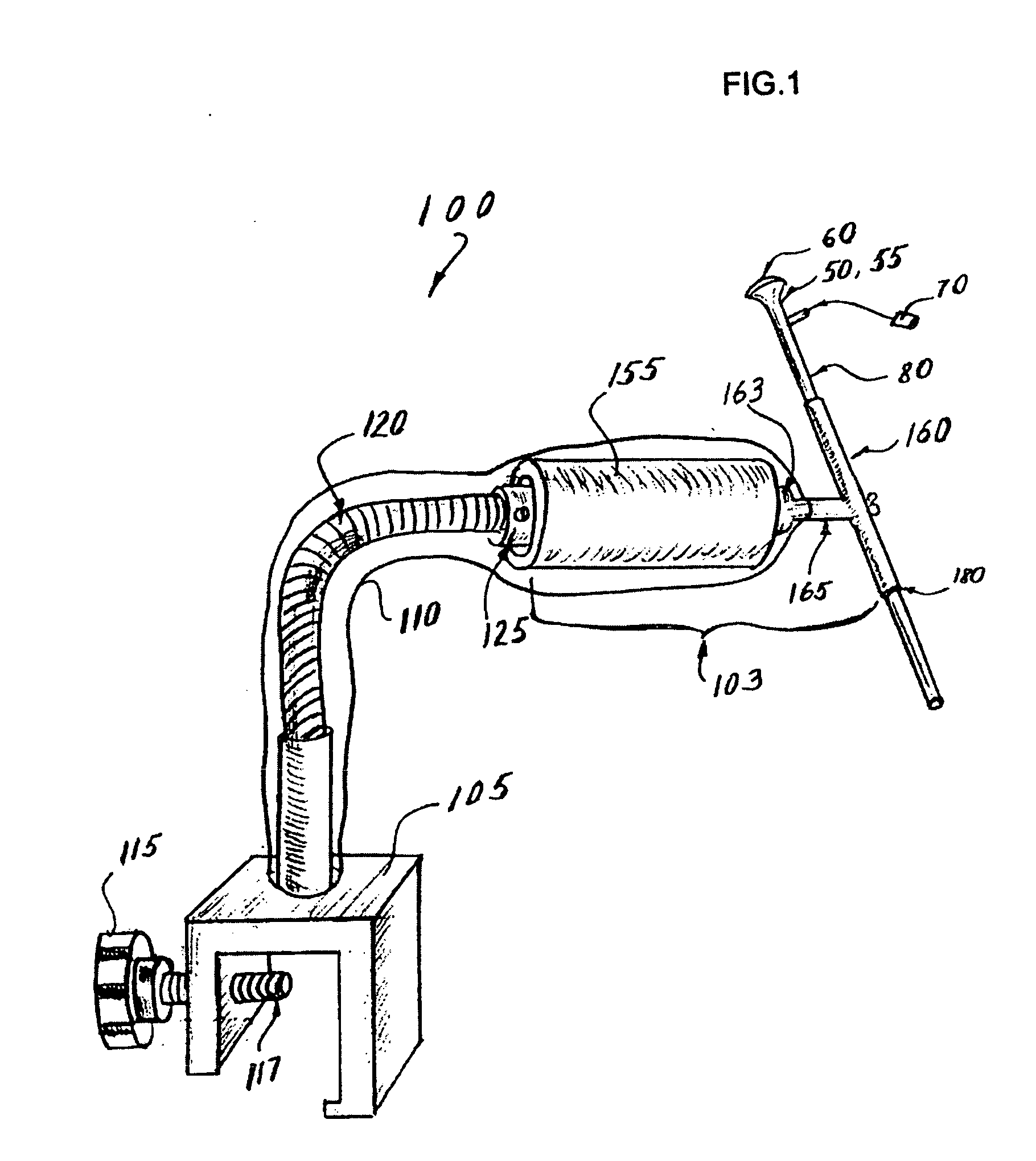
[0026] Reference will now be made in detail to the present preferred embodiment(s) of the invention, examples of which are illustrated in the accompanying drawings. Whenever possible, the same reference numerals will be used throughout the drawings to refer to the same or like parts. One embodiment of the present invention is shown in FIG. 1, and is designated generally throughout by the reference numeral 100.

[0027] More specifically, FIG. I shows a device 100 for holding a medical instrument 50. The medical instrument 50 is, for example, a typical laparoscopic camera 55 having an eyepiece 60, connector for the light source 70 and a sheath or shaft 80. The device 100 for holding a medical instrument includes a base unit 102 and an adjustable holder 103 that supports the medical instrument in the desired position and also allows 360° rotation and X-Y-Z motion of the medical instrument, as needed.

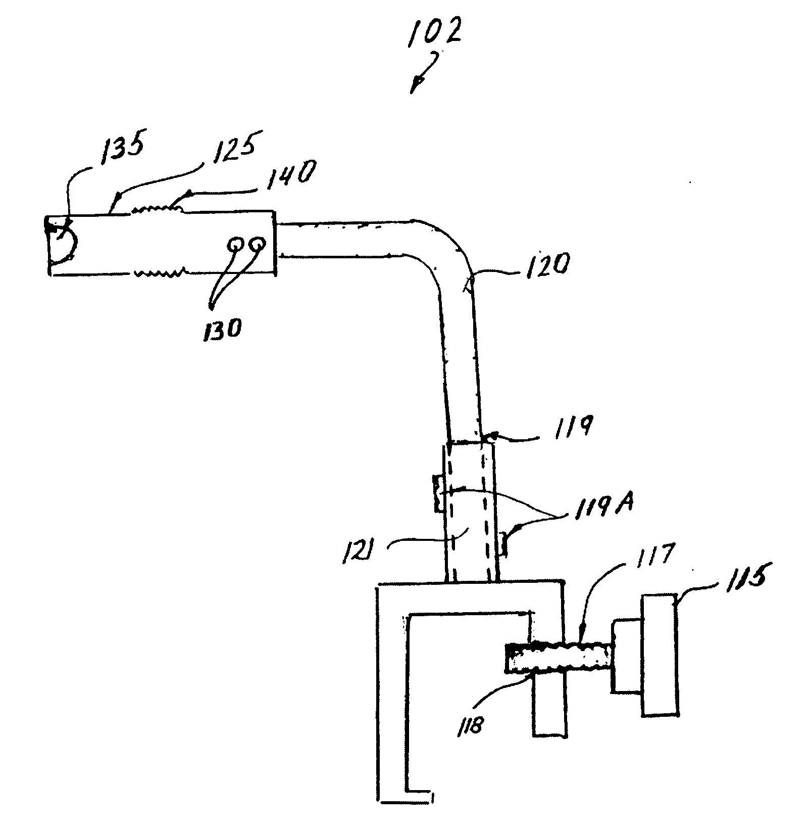
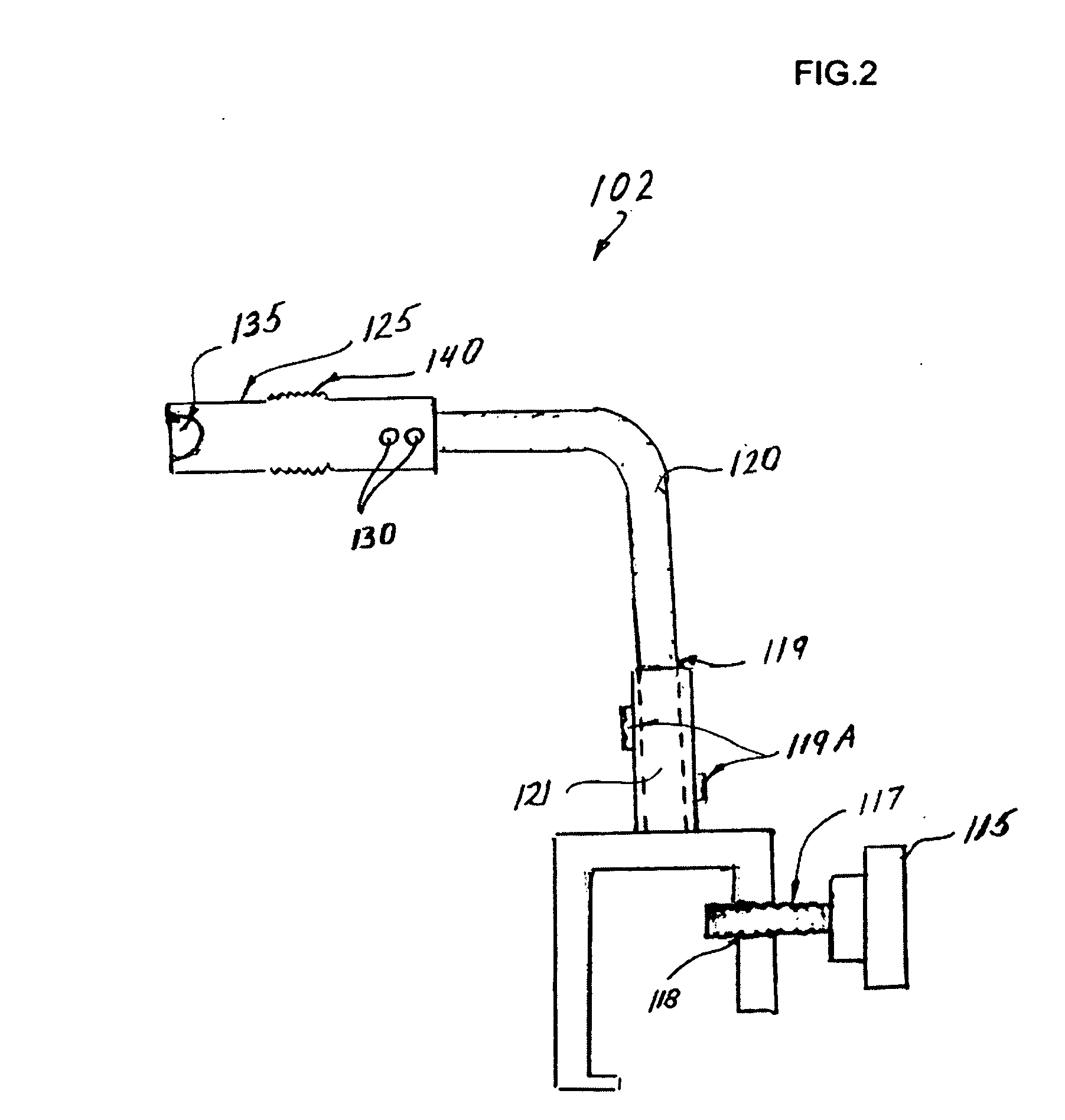
[0028] The base unit 102 is shown schematically in FIG. 2 and includes a clamp 105 for ...


PUM


Abstract

According to one aspect of the invention, a device for holding a medical instrument comprises: (i) a hose including a first engagement element, the hose being position adjustable without the use of pressurized fluid; and (ii) an instrument holder with a second engagement element, wherein said first and the second engaging elements form a single ball and socket joint.

Description

BACKGROUND OF THE INVENTION [0001] The present invention relates to improvements in diagnostic and surgical procedures, and especially to flexible holders for the stabilization of laparoscopes or other endoscopic instruments or surgical retractors used during diagnostic or surgical procedures. More particularly the invention relates an improved holder clamp which may be situated near the operating or examination table for supporting an endoscope, a retractor or the like. TECHNICAL BACKGROUND [0002] Laparoscopic surgery is a procedure in which surgical instruments and a viewing scope, for example, laparoscope, are inserted through respective small puncture wounds or incisions into the abdominal cavity of a patient. A small video camera is attached to the laparoscope and connected to a television monitor for viewing the procedure. [0003] The instruments and the laparoscope are inserted through cannulae which are first inserted through the incisions. Cannulae are hollow tubes with gas ...

Claims


Application Information

Patent Timeline
IPC IPC(8): A61B17/00
CPCA61B17/00234A61B19/26A61B2017/2905A61B2019/268F16M11/046F16M2200/027F16M11/2078F16M11/40F16M13/02F16M13/022F16M2200/022F16M11/14A61B1/00149A61B90/50A61B2090/571
Inventor SHILKRUT, ALEXANDER
Owner SHILKRUT ALEXANDER
Learn More