Vacuum cleaner

Active Publication Date: 2006-11-23
SAMSUNG GWANGJU ELECTRONICS CO LTD
View PDF6 Cites 22 Cited by
  • Summary
  • Abstract
  • Description
  • Claims
  • Application Information

AI Technical Summary

Benefits of technology

[0017] The motor housing comprises an inner housing enclosing the motor body at a predetermined distance and thereby forming a first path, and an outer housing enclosing the inner housing at a predetermined distance, thereby forming a second path, and enclosing the suction fan unit. The inner housing comprises at least one connection opening formed near the suction fan unit to form the first and the second paths, and the outer housing comprises at least one penetrating opening formed on a rear side thereof facing the path extension member. The air drawn in through the suction fan unit and discharged through the motor body is passed sequentially through the first path, the

Problems solved by technology

In the conventional motor assembly as described above, operating noise is generated due to airflow and vibrations induced by rotation of the suction fan.
The operating noise is transmitted to the outside of a cleaner body together with the air being discharged, thereby making a user of the vacuu

Method used


Image

  • Vacuum cleaner
  • Vacuum cleaner
  • Vacuum cleaner

Examples


Example

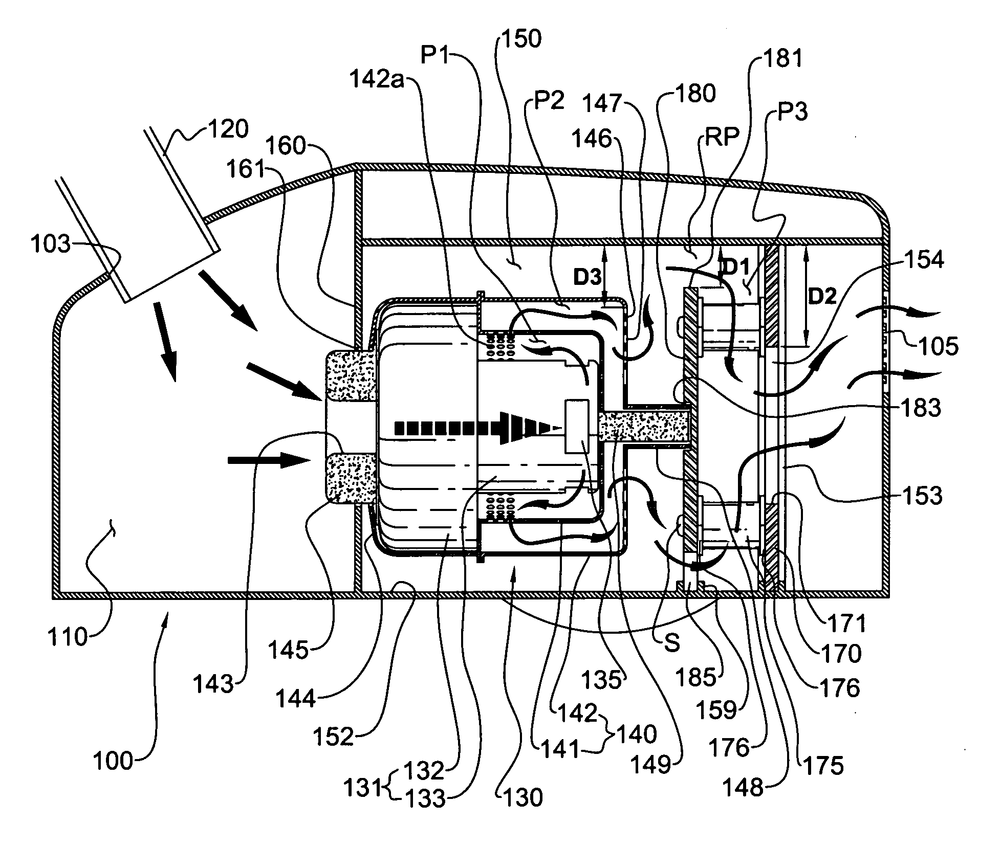
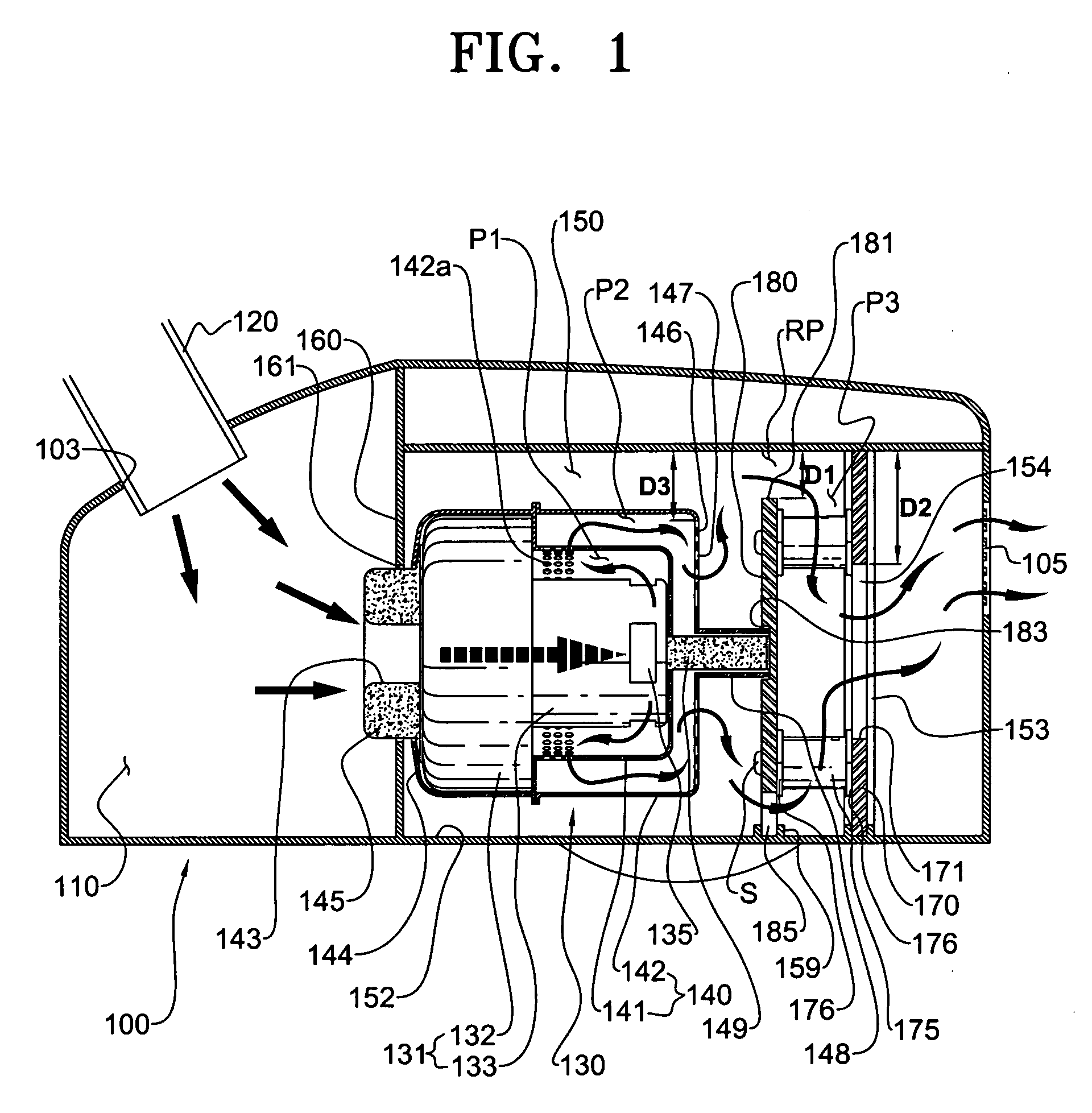
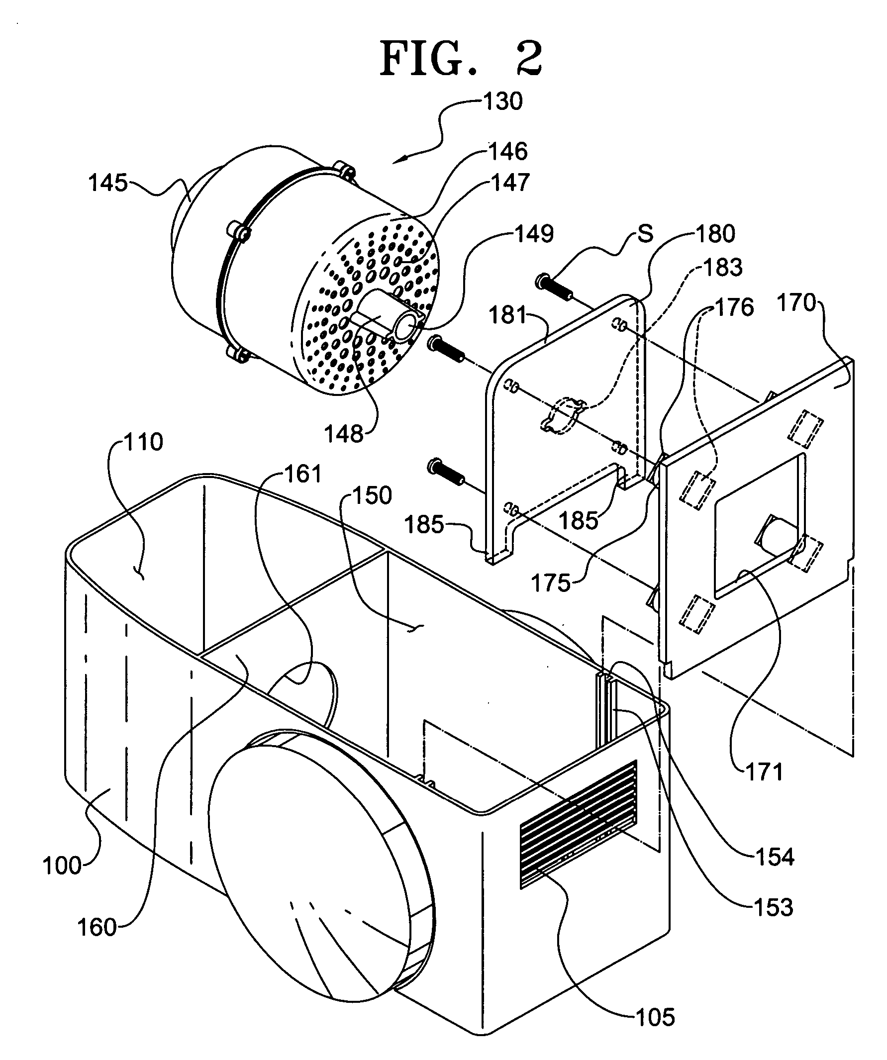
[0026]FIGS. 1 and 2 show a portion of a vacuum cleaner according to a first embodiment of the present invention. The vacuum cleaner according to the first embodiment of the present invention comprises a cleaner body 100 and a suction assembly (not shown). A dust suction port (not shown) is formed at a bottom part of the suction assembly so as to draw in dust-laden air around a surface being cleaned therethrough. As the cleaner body 100 is operated, the dust on the surface being cleaned is drawn in through the dust suction port together with the ambient air. When applied to an upright-type vacuum cleaner, the suction assembly may be pivotably connected to a lower end of the cleaner body. As shown in FIG. 1, when applied to a canister-type vacuum cleaner, the suction assembly is in fluid communication with the cleaner body 100 through a suction means such as an extension pipe (not shown) or an extension hose 120 connected with an insertion opening 103 penetratingly formed on the clean...

Example

[0034]FIG. 4 shows second and third partitions according to a second embodiment of the present invention. The third partition 180′ of the second embodiment comprises a plurality of first noise-absorption projections 200 formed on a surface thereof. Additionally, a plurality of second noise-absorption projections 210 having the same structure as the first noise-absorption projections 200 of the third partition 180 are formed on a surface of the second partition 170′. As the air flowing through the detour path RP and the third path P is contacted with the second partition 170′ and the third partition 180′, the first and the second noise-absorption projections 200 and 210 help diffuse the operating noise being transmitted together with the airflow, thereby effectively reducing the noise transmitted to the outside of the cleaner body 100.

[0035] Here, configuration of the surfaces of the second and the third partitions 170′ and 180′ is not limited to the noise-absorption projections 200...


PUM


Abstract

A vacuum cleaner is disclosed which comprises a motor chamber for mounting a motor assembly that, generates a suction force at a dust suction port, and a discharge port for guiding an air discharged from the motor chamber to the outside of a cleaner body, wherein the motor chamber comprises an air discharge opening which is in fluid communication with the discharge port; and a path extension member disposed between the motor assembly and the air discharge opening, of which edges are spaced apart from an inner wall of the motor chamber by a predetermined distance, respectively, to thereby form a detour path, and the air discharged from the motor assembly is guided in a circuitous manner by the path extension member so as to be passed through the detour path before reaching the air discharge opening. That assembly effectively reduces noise generated during operation of the motor assembly that is detectable outside of the cleaner body.

Description

CROSS-REFERENCE TO RELATED APPLICATIONS [0001] This application claims benefit under 35 U.S.C. § 119(a) of Korean Patent Application No. 2005-41441, filed May 18, 2005, the entire contents of which are incorporated herein by reference. BACKGROUND OF THE INVENTION [0002] 1. Field of the invention [0003] The present invention relates to vacuum cleaners. More particularly, the present invention relates to a motor chamber of a vacuum cleaner, which is formed in a cleaner body for mounting a motor assembly that generates a suction force. [0004] 2. Description of the Related Art [0005] Generally, vacuum cleaners include a motor assembly that generates a suction force at a suction port for drawing in impurities (hereinafter, referred to as ‘dust’) on a surface being cleaned together with ambient air. The motor assembly comprises a suction fan unit having a suction fan, and a motor body rotating the suction fan unit. The motor body has therein a stator, and a rotor rotated by electromagneti...

Claims


Application Information

Patent Timeline
IPC IPC(8): A47L9/22
CPCA47L9/22A47L9/0081A47L9/00
Inventor SONG, HWA-GYULEE, SUNG-CHEOLOH, HYUN-JUN
Owner SAMSUNG GWANGJU ELECTRONICS CO LTD
Why Eureka
Try Eureka