Rotary cutting apparatus

a cutting machine and rotary blade technology, applied in the field of rotary cutting machines, can solve the problems of deteriorating the appearance of products, high accuracy, and difficult assembly, and achieve the effects of reducing wind noise, ensuring and stably cutting, and increasing the rotation speed of the rotary blad

Inactive Publication Date: 2006-11-23
NKG
View PDF18 Cites 9 Cited by
  • Summary
  • Abstract
  • Description
  • Claims
  • Application Information

AI Technical Summary

Benefits of technology

[0037] In the rotary cutting apparatus according to the fifth aspect, since the inertia moment of the rotary blade is increased by arranging a plurality of weights at equal intervals on the rotating circumference of the rotary blade, the rotational force of the rotary blade caused by the function of intake air is increased, and it is possible to surely and stably perform cutting between the cutting blade on the outer circumference of the rotary blade and the blade holes of the fixed blade. Moreover, such cutting is realized without increasing the rotation speed of the rotary blade, and it is possible to reduce wind noise caused by the rotation of the rotary blade.
[0038] In the rotary cutting apparatus according to the sixth aspect, since the w...

Problems solved by technology

Textile products such as clothes and carpets have the problem that fibers on their surface are gathered into pills by the function of friction applied during use and deteriorate the appearance of the products.
However, since the fixed blade is a thin plate fixed and supported along the opening of the housing and the housing is a molded product made of resin for which it is hard to obtain high accuracy of form, it is difficult to perform assembling by eliminating a clearance between the cutting blade of the rotary blade and the blade holes of the fixed blade.
However, since a rotary cutting apparatus constructed to cut and remove pills created on the surface of a textile product may be used for large-area textile products such as carpets, the size of the fixed blade is inevitably large as well as the rotary blade and the housing.
Thus, similarly to the shaver, it is difficult to eliminate the clearance by improving the molding and processing precisions of the fixed blade.
However, since the rotational force actually obtained by such a rotary blade is...

Method used


Image

  • Rotary cutting apparatus
  • Rotary cutting apparatus
  • Rotary cutting apparatus

Examples


Embodiment Construction

[0052] A description of preferred embodiments of the invention follows.

[0053] While this invention has been particularly shown and described with references to preferred embodiments thereof, it will be understood by those skilled in the art that various changes in form and details may be made therein without departing from the scope of the invention encompassed by the appended claims.

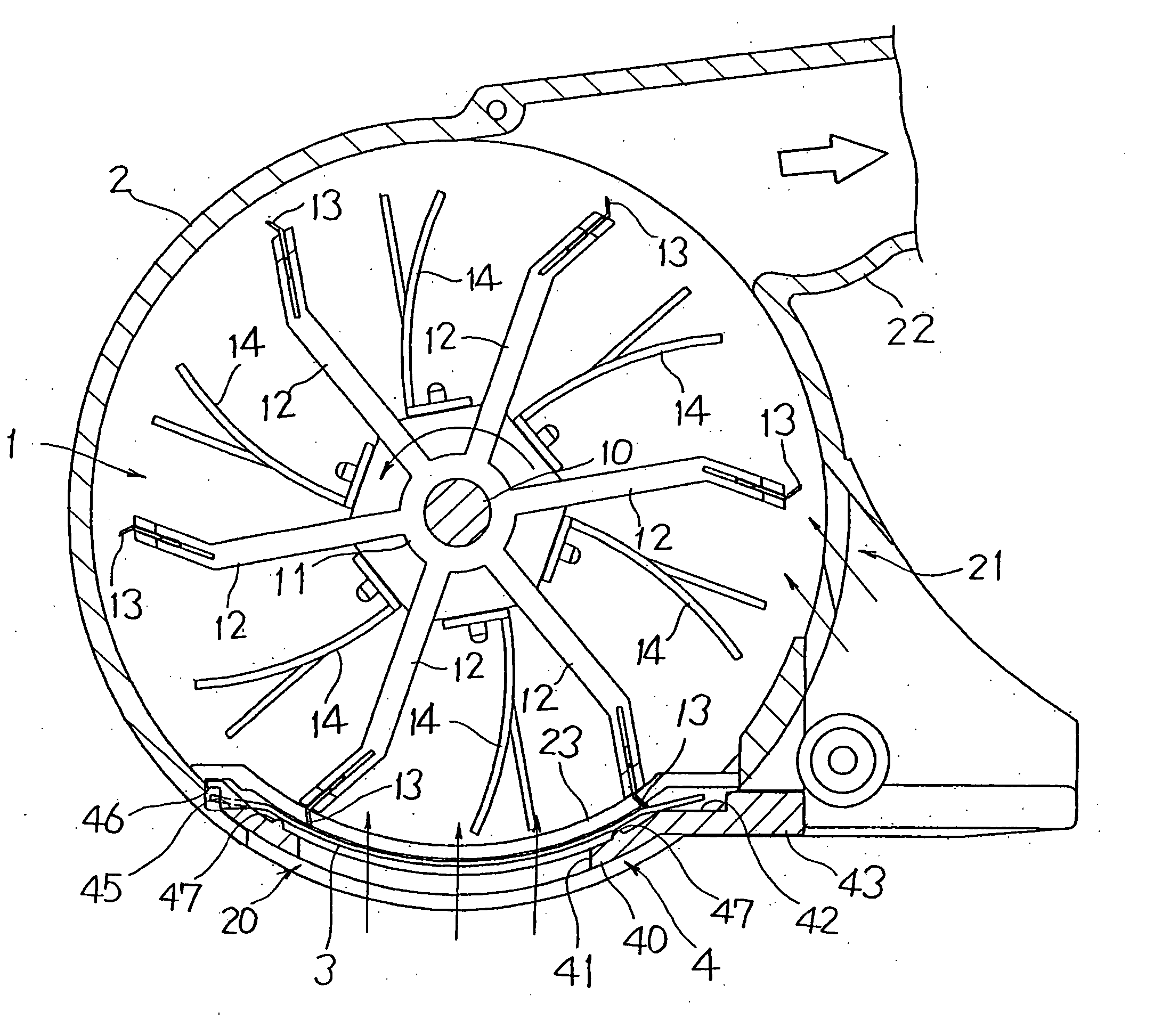
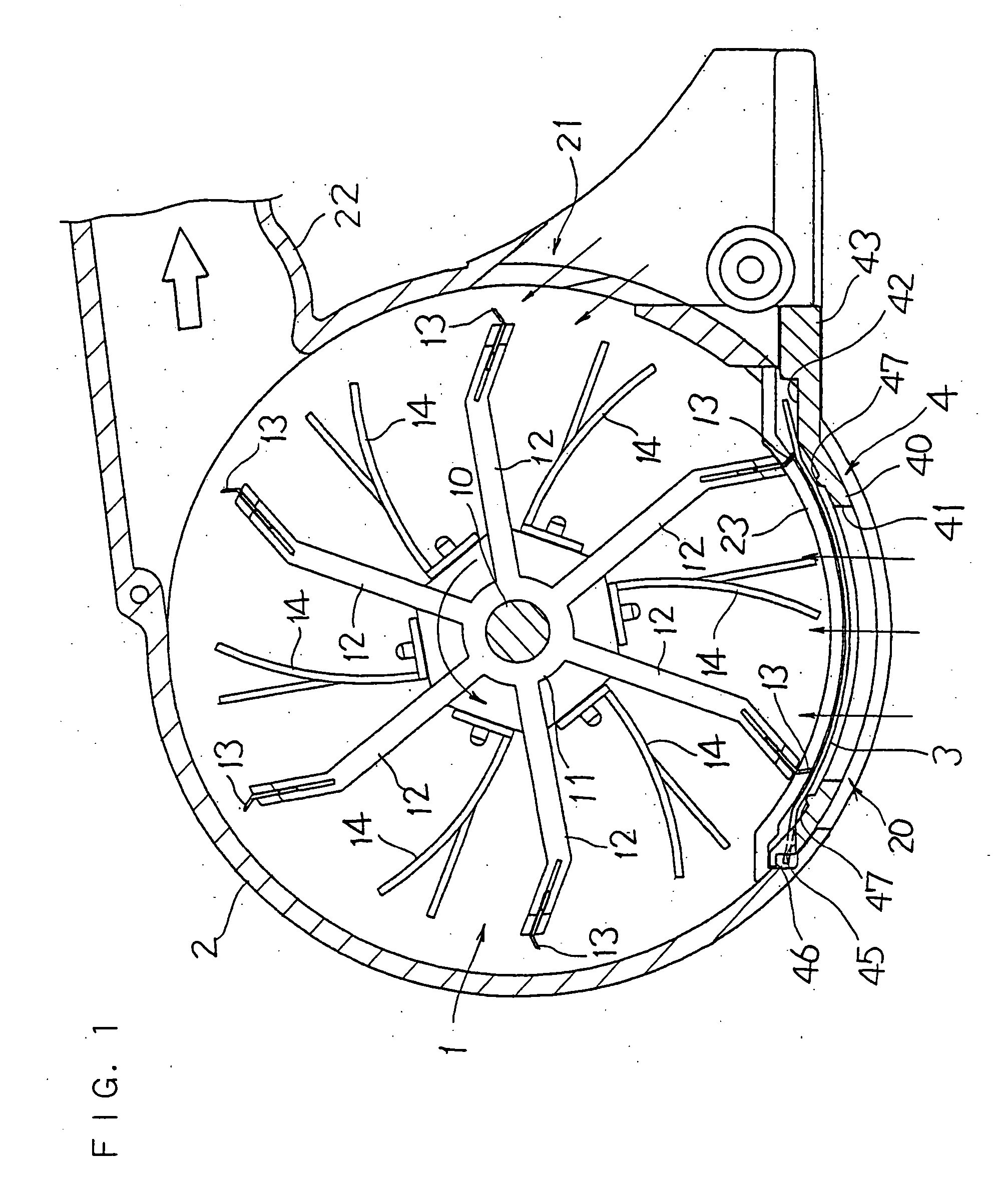
[0054] The following description will explain in detail the present invention, based on the drawings illustrating an embodiment thereof. FIG. 1 is a sectional side view of a rotary cutting apparatus of the present invention. As shown in FIG. 1, the rotary cutting apparatus comprises a rotary blade 1, a housing 2 for accommodating the rotary blade 1, and a fixed blade 3 in the form of a plate.

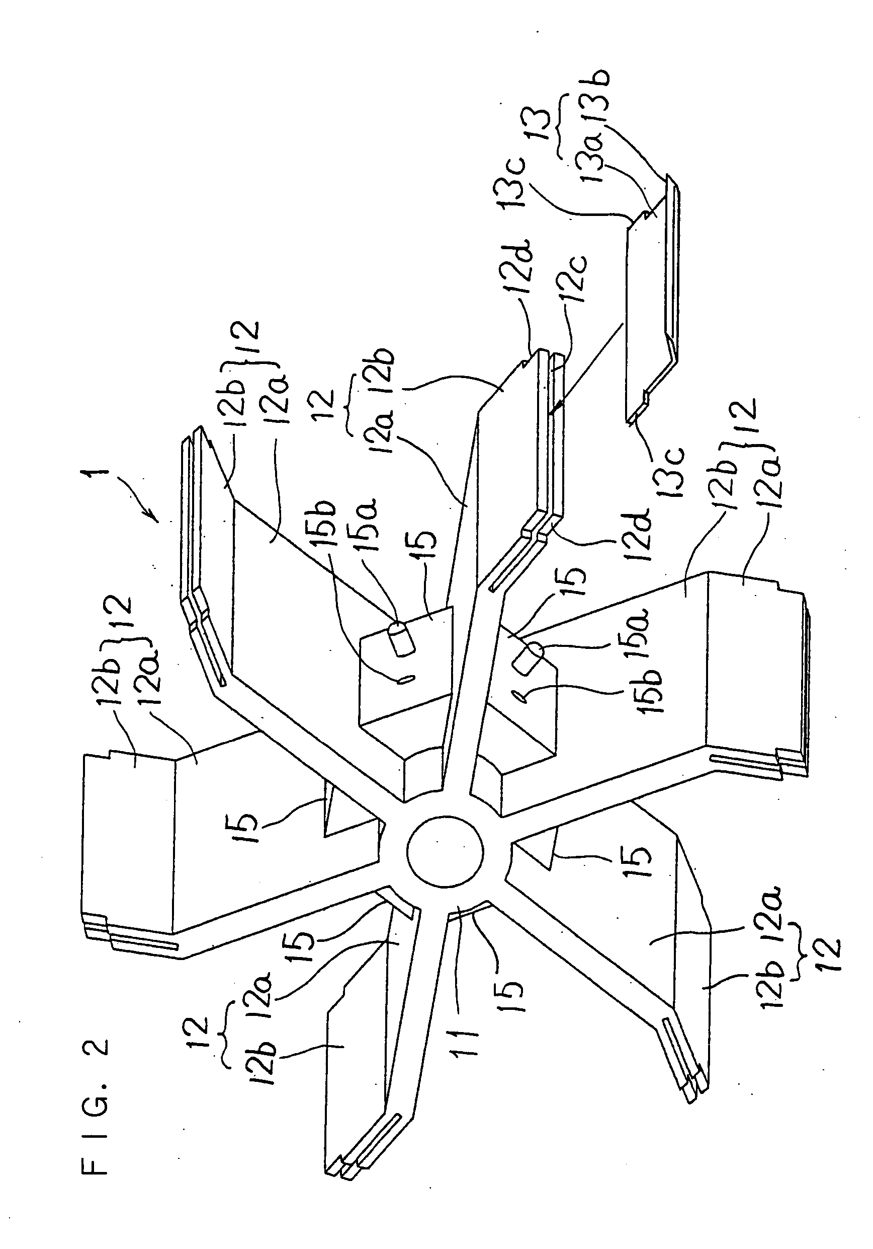
[0055] The rotary blade 1 is constructed as an impeller integrally comprising a plurality of (six in FIG. 1) vanes 12, 12 . . . which are arranged at equal intervals in a circumferential direction and protrude ou...


PUM

PropertyMeasurementUnit
Weightaaaaaaaaaa
Forceaaaaaaaaaa
Widthaaaaaaaaaa

Abstract

In a rotary cutting apparatus, including a rotary blade having a cutting blade on the outer circumference and rotating radially in one direction; a housing for accommodating the rotary blade; and a fixed blade in the form of a plate attached to the housing along the outer circumference of the rotary blade, for cutting objects protruding from the blade holes of the fixed blade into the housing by the function of the cutting blade of the rotary blade that comes into slide-contact with the inner surface of the fixed blade, the fixed blade is supported at only one end by hooking one edge of the fixed blade on an upstream side in a rotation direction of the rotary blade onto a hook protrusion, and attached so that it is freely displaceable in an in-plane direction and a direction crossing the plane.

Description

RELATED APPLICATION(S) [0001] This non-provisional application claims priority under 35 U.S.C. §119(a) on Patent Application No. 2005-146989 filed in Japan on May 19, 2005 and Patent Application No. 2005-146990 filed in Japan on May 19, 2005, the entire contents of which are hereby incorporated by reference. BACKGROUND OF THE INVENTION [0002] 1. Field of the Invention [0003] The present invention relates to a rotary cutting apparatus for use in cutting and removing objects such as pills created on the surface of a textile product. [0004] 2. Description of Related Art [0005] Textile products such as clothes and carpets have the problem that fibers on their surface are gathered into pills by the function of friction applied during use and deteriorate the appearance of the products. Conventionally, a rotary cutting apparatus aiming at cutting and removing such pills has been proposed (see, for example, Japanese Patent Application Laid-Open No. 07-88797 (1995)). [0006] This rotary cutti...

Claims


Application Information

Patent Timeline
IPC IPC(8): B26D1/18
CPCB26D1/03B26D7/0691B26D7/00B26D1/38Y10T83/7776
Inventor OHSUGI, YASUHIRO
Owner NKG
Why Eureka
Try Eureka