Method of transfer printing

Inactive Publication Date: 2006-11-23
TAN MING FENG
View PDF5 Cites 1 Cited by
  • Summary
  • Abstract
  • Description
  • Claims
  • Application Information

AI Technical Summary

Benefits of technology

[0008] The primary objective of the present invention is to provide a method of transfer printing, and more particularly to a method wherein an adhesive of a solvent-type is first pasted on a surface of an object, then a transfer film is covered on the surface of object when the adhesive volatilizes to a half-dry condition, next a pressure is exerted according to a type of object in order to uniformly glue an ink of the transfer film on the object, and finally a plastic film on a surface of the transfer film is removed, thereby accomplishing the transfer printing.
[0011] Furthermore, in the method of transfer printing, as the pressure exerted can be controlled according to the form and type of object, the object will not be broken by the pressure during the process of exerting pressure.

Problems solved by technology

There are many drawbacks of an existing thermal transfer printing technique:
The processing cost is high.
A lot of thermal energy needs to be consumed for the thermal transfer printing, wherein a large quantity of expensive thermally molten glues is used.
It is difficult to guarantee the quality of processing.
A physical effect of expanding in hot and shrinking in cold will be generated to a processed object due to the necessity of heating up, which results in the difficulty in controlling the stability of dimension of the processed object after performing the transfer printing.
If a product needs to go through 2nd or more processing procedures, all kinds of drawbacks such as a higher total defect rate, an inferior stability of dimension of printing, and instability of relative position of cutting will occur.
However, temperature in an ambient environment has a large effect on the cooling efficiency of the processed object; therefore, the size of storing space and whether the processed object can be completely cooled down remain unknown.
It is difficult to control the necessary size of the storing space, and the time needed for completely cooling down the processed object.
If elongation and a breaking strength of the ink itself are not as high as those of the processed object, the phenomenon of shrinking in cold of the processed object, after being cooled down, will generate a local cracking to the ink that has been printed transferring.
However, an oven of an ordinary printing station will not be long enough for this faster speed and hence cannot completely dry the ink.
Nevertheless, the printing machine with the lengthened oven is a special machine with few quantities on the market, and vendors who can supply are too few, thereby causing a higher price to this kind of transfer film.
On the other hand, when products of thermal transfer printing are used in higher temperature, the viscosity of adhesive will be reduced with an increase of temperature (usually as high as 90 degree Celsius), or even the adhesive can be totally damaged, as a thermally molten glue is used as the adhesive.
It is not suitable for processing a closed-cell linking foam work-piece.
As the bubbling material is heated up, the balloons inside the organization will be swelling, thereby enlarging the dimension of original work-piece.
However, the dimension of transfer film to be printed transferring is fixed; It's so difficult to match together with them.
If a thermal transfer printing process is performed to a processed object with the original dimension, the dimension of pattern on the transfer film will be shrunk when the processed object is completely cooled down after accomplishing the thermal transfer printing, and the higher the temperature of heating, the more severe the shrinking of the dimension of the pattern.
If a continuous transfer printing is needed for a product, the dimension of length of the processed object should be increased during being heated up, and the extra length will not fit with the dimension of transfer film without change of dimension.
Hence, one of every two or three patterns cannot be used completely.
After performing the transfer printing to a whole roll, the dimension of each pattern will be different, resulting in extreme difficulty in the processing of next working procedure.

Method used


Image

  • Method of transfer printing
  • Method of transfer printing
  • Method of transfer printing

Examples


Embodiment Construction

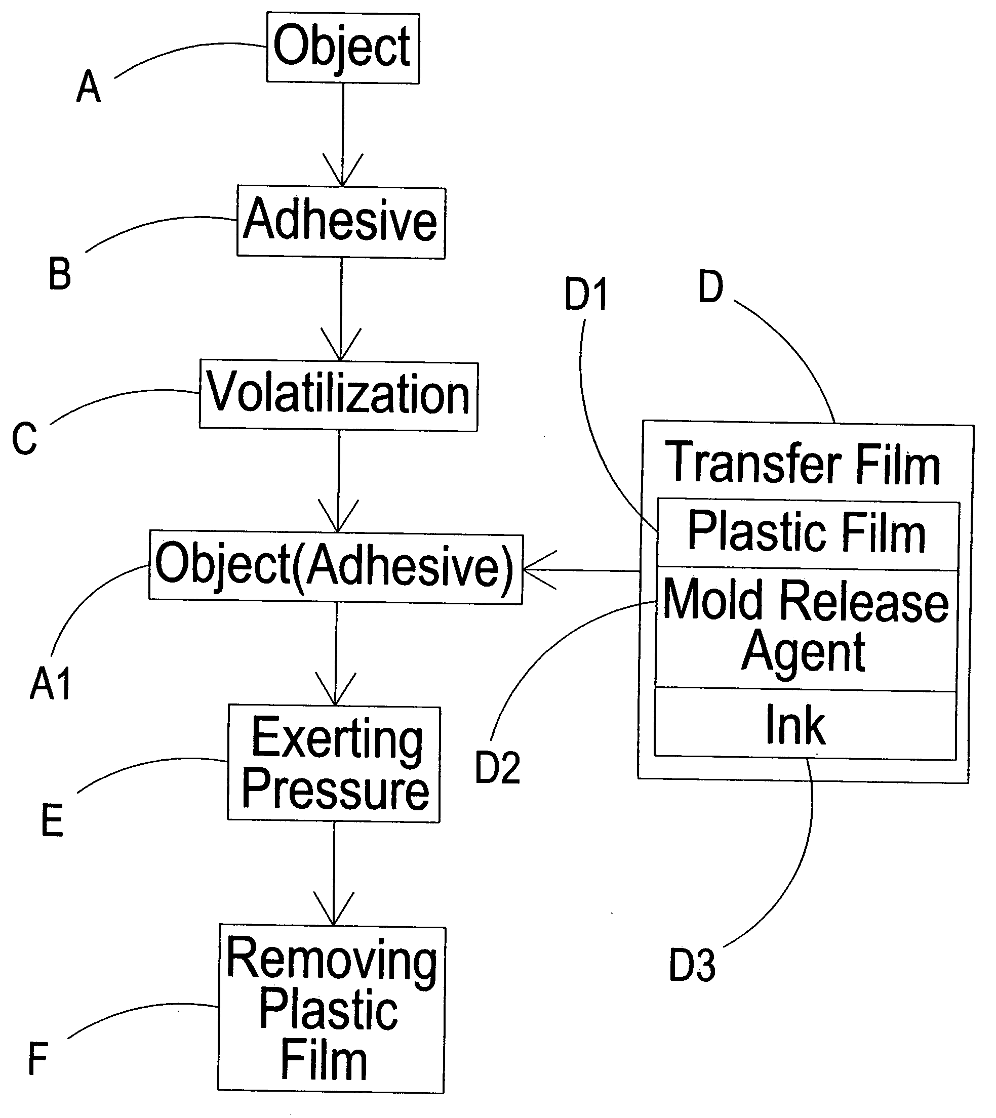
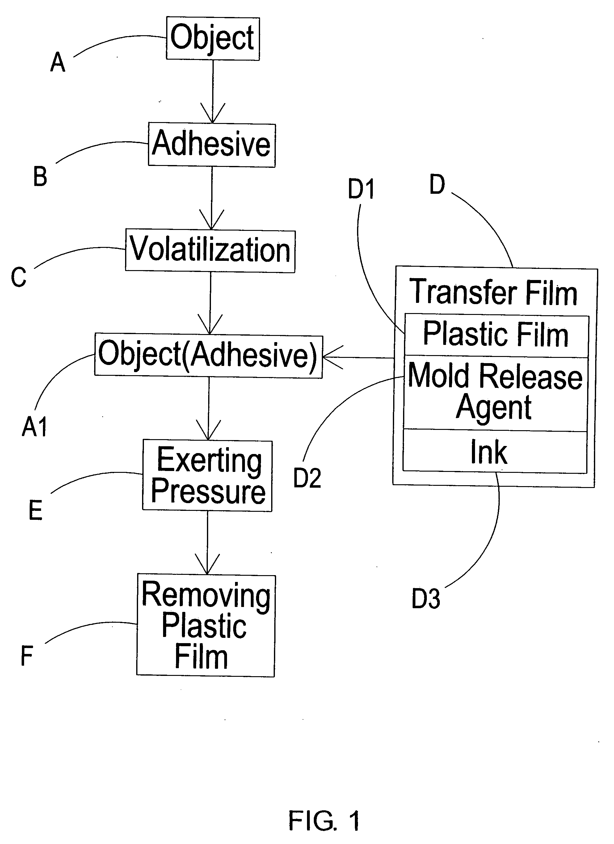
[0021] As shown in FIG. 1, which is a workflow consisting of an object A, an object (adhesive) A1, an adhesive B, volatilization C, a transfer film D, exerting pressure E, and removing a plastic film F. The transfer film D is provided with a plastic film D1, a mold release agent D2, and an ink D3, wherein the ink D3 is glued on the plastic film D1 through the mold release agent D2.

[0022] A feature of the workflow lies in that under a condition of normal temperature of about 10 to 45 degree Celsius, the adhesive of a solvent-type B is uniformly pasted on the object to be printed transferring A, and to uniformly cover the transfer film D on the object (adhesive) A1 after the adhesive B volatilizes to 40 to 60% (about a level of not sticking a hand upon touching the adhesive B).

[0023] A pressure E is exerted on the object (adhesive) A1 covered with the transfer film D. Depending on the form and type of the object A, the pressure exerted E is about 5 to 100 kilograms.

[0024] After acc...


PUM


Abstract

A method of transfer printing includes first pasting an adhesive of a solvent-type on an object, then covering a transfer film on the object under a condition of half-dry of the adhesive, and next exerting pressure according to a form of the object for uniformly gluing an ink of the transfer film onto the object, and finally tearing off a plastic film on a surface of the transfer film, thereby accomplishing the transfer printing. In addition, a mold release agent is pasted between the plastic film and the ink, and the viscosity of the adhesive is larger than that of the mold release agent, so as to uniformly and firmly attach the ink to the object, and to remove the mold release agent along with the plastic film, during the aforementioned workflow.

Description

BACKGROUND OF THE INVENTION [0001] (a) Field of the Invention [0002] The present invention relates to a method of transfer printing, and more particularly to a method wherein an adhesive of a solvent-type and a mold release agent between a plastic film and ink is used to accomplishing the transfer printing. [0003] (b) Description of the Prior Art [0004] There are many drawbacks of an existing thermal transfer printing technique: [0005] 1. The processing cost is high. A lot of thermal energy needs to be consumed for the thermal transfer printing, wherein a large quantity of expensive thermally molten glues is used. The working procedure of processing is long, such that a large space should be occupied for entire machinery equipment. [0006] 2. It is difficult to guarantee the quality of processing. A physical effect of expanding in hot and shrinking in cold will be generated to a processed object due to the necessity of heating up, which results in the difficulty in controlling the st...

Claims


Application Information

Patent Timeline
IPC IPC(8): B41F3/34
CPCB41F16/00B44C1/1712B41M5/025
Inventor TAN, MING-FENG
Owner TAN MING FENG
Why Eureka
Try Eureka