Composite rim manufacturing method and structure

A composite, rim-based technology, applied to other household appliances, household appliances, household components, etc., can solve problems such as troublesome and time-consuming construction, poor combination of carbon fiber rims and tires, and air leakage, etc., to improve safety performance and durability, improving production efficiency and yield, and reducing manufacturing costs

Inactive Publication Date: 2020-06-02
ALEX GLOBAL TECH
View PDF8 Cites 1 Cited by
  • Summary
  • Abstract
  • Description
  • Claims
  • Application Information

AI Technical Summary

Problems solved by technology

[0002] The existing carbon fiber rim molding technology mainly inflates a ring-shaped airbag, and then covers the outer surface of the airbag with multiple layers of carbon fiber cloth in sequence. However, due to the softness of the airbag, carbon fiber cloth is pasted on the surface of the airbag The construction of the material is quite troublesome and time-consuming, especially on the soft airbag, the carbon fiber cloth material is difficult to be flattened, therefore, the defect rate of the existing carbon fiber rim increases and other problems
[0003] Furthermore, after stacking multiple layers of carbon fiber cloth to form a rim shape, the carbon fiber must be hardened through heating and other procedures. However, the carbon fiber lacks ductility after hardening and setting. At the same time, the carbon fiber rim is not resistant to impact force, and is prone to breakage and damage. The carbon fiber rim stacked and covered by multiple layers of carbon fiber cloth cannot be formed at the upper end of the two side walls and can be fixed with the bead of the tire. At most, the protruding ribs can only use the method of stacking carbon fiber cloth to form a slightly arc-protruding flange, so that the existing carbon fiber rim and tire are not well bonded and fixed, except that the tire and the rim are prone to fall off. , when applied to tubeless rims, problems such as air leakage will occur due to poor fit, which will affect the safety of bicycle riding

Method used


Image

  • Composite rim manufacturing method and structure
  • Composite rim manufacturing method and structure
  • Composite rim manufacturing method and structure

Examples


Embodiment Construction

[0042] In order to make the technical means of the present invention and the effects it can achieve more completely and clearly disclosed, the detailed description is as follows, please refer to the disclosed drawings and figure numbers:

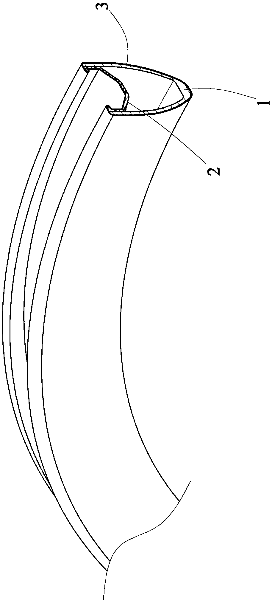
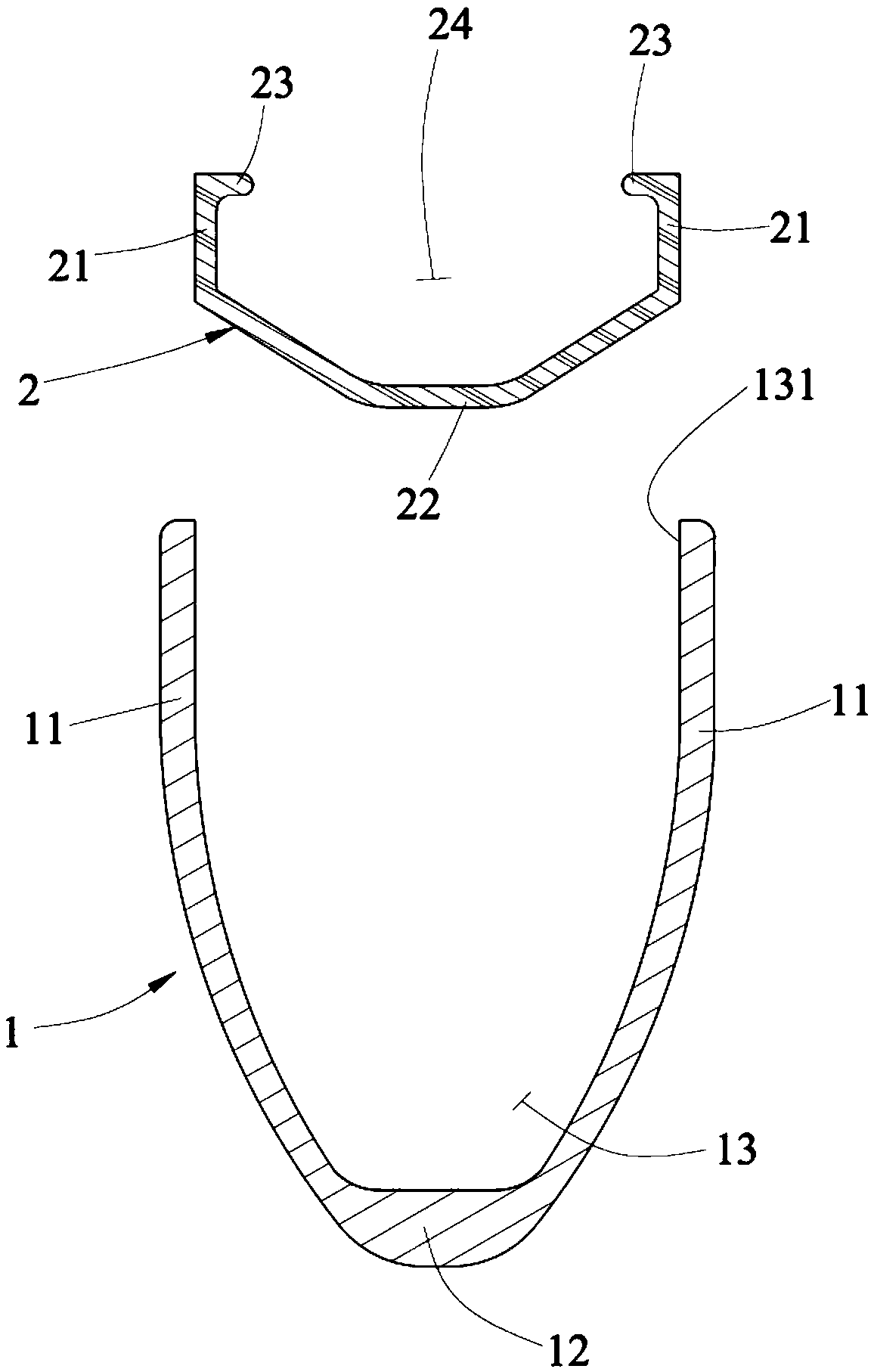
[0043] First, see figure 1 , figure 2 Shown, be the composite rim method of the present invention, its main implementation steps include:

[0044] A. Forming the main body of the rim: prepare a rim main body molding mold, and a mold cavity is provided in the rim main body molding mold, and multiple layers are sequentially pasted along the cavity wall of the rim main body molding mold The first carbon fiber material, the first carbon fiber material can be carbon fiber cloth material, and then the first carbon fiber material is heated and hardened in the rim body forming mold to form a ring-shaped rim body 1, please see also image 3 As shown, the section of the rim main body 1 is formed with two opposite side walls 11 and a bottom wall 12...


PUM


Abstract

The invention relates to a composite rim manufacturing method and structure, A rim body made of carbon fibers is mainly formed in a mold cavity of a rim body forming mold, a rim assembly is formed through extrusion of metal materials, and the rim assembly and the rim body are combined, so that the surfaces of the combined rim body and rim assembly are rightly coated with a rim coating layer made of carbon fibers, in this way, through the composite rim manufacturing method and structure, the manufacturing efficiency of a rim can be improved, the yield of the rim can be increased, the purpose ofmaking the rim lightweight is achieved, and the rim manufacturing cost is lowered; and through stable embedding of tire embedded ribs at the upper end of the rim assembly made of the metal materialsand tire lips of a tire, the situations of air leakage, falling-off and the like of the tire can be prevented, through the ductility of the rim assembly made of the metal materials and cooperating with the rigidity of the rim body made of the carbon fibers, road jumping vibration impact is borne, so that the rim is not broken or damaged, and in this way, the safety and durability of the rim in useare improved.

Description

technical field [0001] The invention relates to a compound rim manufacturing method and its structure, especially to a method that can improve the production efficiency and yield of the rim and reduce its cost, and can improve the safety and durability of the rim in use, and achieve the A composite wheel rim manufacturing method and structure with benefits such as light weight. Background technique [0002] The existing carbon fiber rim molding technology mainly inflates a ring-shaped airbag, and then covers the outer surface of the airbag with multiple layers of carbon fiber cloth in sequence. However, due to the softness of the airbag, carbon fiber cloth is pasted on the surface of the airbag The construction of the material is quite troublesome and time-consuming, especially on the soft airbag, the carbon fiber cloth material is difficult to flatten and cover, therefore, causing problems such as an increase in the defect rate of the existing carbon fiber rim. [0003] Fu...

Claims


Application Information

Patent Timeline
Patent Type & Authority Applications(China)
IPC IPC(8): B29D99/00B29C70/30B29C70/68
CPCB29C70/30B29C70/68B29D99/0082
Inventor 陈威瑾
Owner ALEX GLOBAL TECH
Why Eureka
Try Eureka