Thermal management of systems having localized regions of elevated heat flux

a technology of heat flux and thermal management, applied in the field of heat transfer, can solve the problems of accelerating failure rate, affecting the performance of the entire chip, and reducing the operational speed of the entire chip by some 10%-15%

Inactive Publication Date: 2006-11-23
MARYLAND UNIV OF
View PDF24 Cites 27 Cited by
  • Summary
  • Abstract
  • Description
  • Claims
  • Application Information

AI Technical Summary

Problems solved by technology

The inability for a CMOS “macrocell” to shed this excess heat from the high-heat flux hot-spot may result in a decrease in the operational speed thereof by some 10%-15%.
As such, the performance of the entire chip is severely compromised and such micro

Method used


Image

  • Thermal management of systems having localized regions of elevated heat flux
  • Thermal management of systems having localized regions of elevated heat flux
  • Thermal management of systems having localized regions of elevated heat flux

Examples


Embodiment Construction

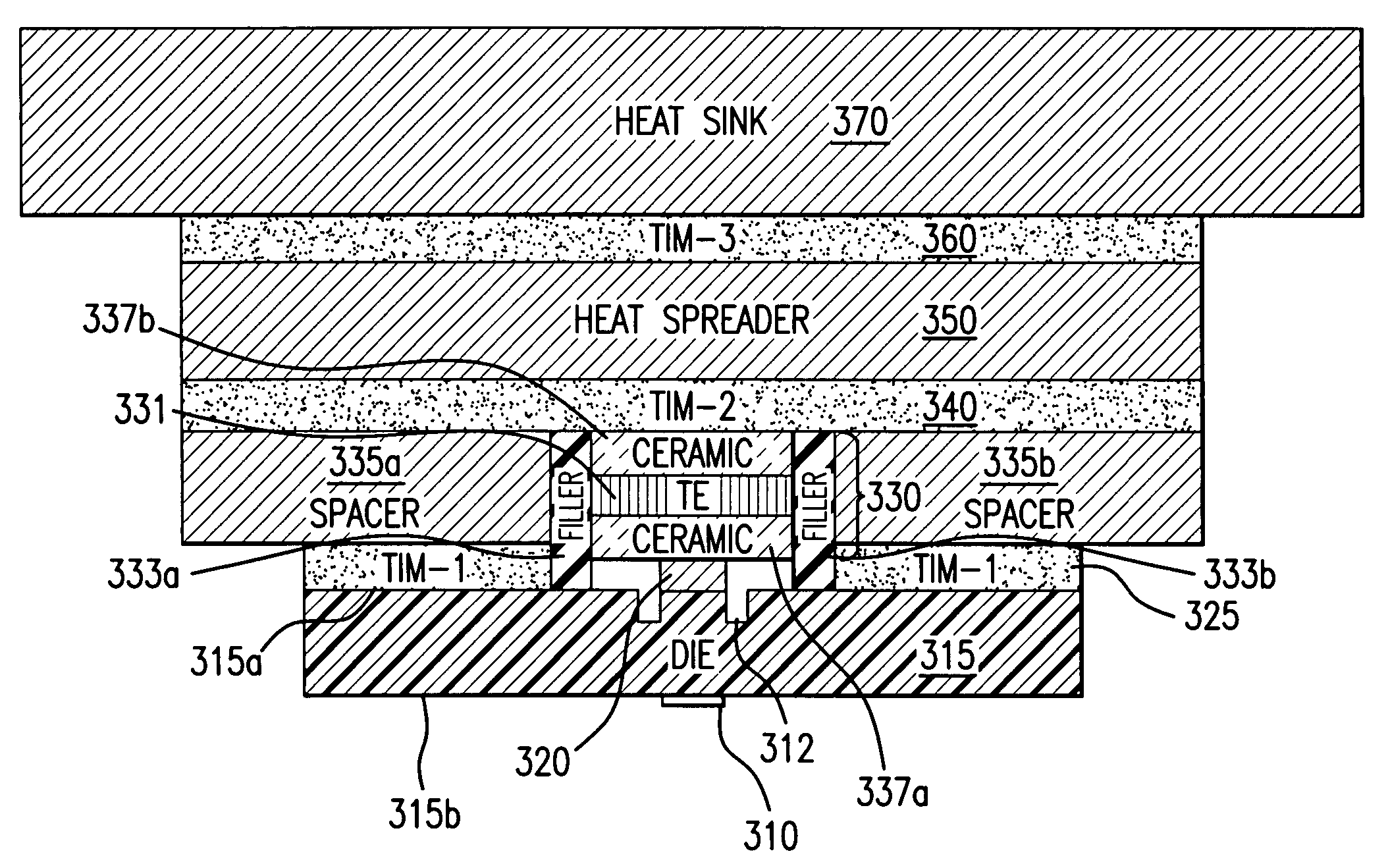
[0023] Referring now to FIG. 3A, there is shown in cross-section an exemplary embodiment of the present invention for illustrating certain beneficial features thereof. It is to be noted that the embodiments described herein are given to illustrate the various aspects of the invention in view of the objectives thereof, and their presentation is not to be construed as limitation of the invention to any particular application. Other configurations and possibilities will be apparent to those skilled in the art upon reading this disclosure.

[0024] As shown in FIG. 3A, an integrated circuit (IC) die 315 has a first surface 315a and a second surface 315b. The die 315 may be composed of any material, but for purposes of explanation, the material of die 315 is of a type typical to the manufacture of ICs, such as Si or GaAs. The circuit constructed on circuit die 315 creates by virtue of its configuration a local hot-spot 310, which is characterized by a localized region of elevated heat flux...


PUM


Abstract

A thermal management system (300) includes a first heat transfer body (330) for providing a opposing heat flux to at least one localized region of elevated heat flux residing in adjacency to a region of lesser flux, such as on a surface (315a) of a circuit die (315) due to a integrated circuit hot-spot (310). A contact (320, 321 962a, 962b, 970a, 970b or 950) defines a thermal conduction path for the opposing flux. A second heat transfer body (350) is in a heat transport relationship with the first heat transfer boy (330) and a second heat transport relationship with the region of lesser heat flux. In such arrangement, each region of heat flux is provided a thermal solution commensurate with the level of heat flux in the region. For example, the opposing heat flux of an active first heat transfer body (330), such as a thermoelectric cooler, may be provided at the hot-spot (310), while at the same time the lesser heat flux is absorbed by a passive second heat transfer body (350), such as a heat spreader.

Description

RELATED APPLICATION DATA [0001] This application is a Continuation-in-Part of application Ser. No. 11 / 253,593, filed on 20 Oct. 2005, which itself is based on Provisional Patent Application No. 60 / 620,357, filed on 20 Oct. 2004.BACKGROUND OF THE INVENTION [0002] 1. Field of the Invention [0003] The invention described herein is most directly related to the field of heat transfer. More specifically, the invention is directed towards thermal management systems for transferring thermal energy across a boundary that includes one or more localized regions of elevated heat flux. [0004] 2. Description of the Prior Art [0005] Present trends toward greater miniaturization of integrated circuits (IC) have provided motivation for innovative on-chip thermal management systems, in that smaller ICs have associated therewith corresponding increases in transistor densities leading to higher circuit current densities and corresponding increases in the heat flux associated therewith. Adding to modern...

Claims


Application Information

Patent Timeline
IPC IPC(8): H05K7/20
CPCH01L23/34H01L2224/16225H01L23/433H01L24/32H01L2224/16227H01L2224/73253H01L2924/01005H01L2924/01029H01L2924/01052H01L2924/01074H01L2924/01082H01L2924/10158H01L2924/10329H01L2924/14H01L2924/01006H01L2924/01033H01L2924/0132H01L23/367H01L2924/01031H01L2224/2612H01L2924/351H01L2924/00
Inventor YANG, BAOBAR-COHEN, AVRAM
Owner MARYLAND UNIV OF
Why Eureka
Try Eureka