
Storage device for light bulbs

a storage device and light bulb technology, applied in the direction of transportation and packaging, tray containers, packaging goods types, etc., can solve the problems of weak structural structure of packaging, unselected bulbs are left in disarray, and sorting through available bulbs leaves unselected bulbs in disarray, etc., to reduce the cross section dimension

Inactive Publication Date: 2006-11-23
TIZIOS
View PDF8 Cites 17 Cited by
  • Summary
  • Abstract
  • Description
  • Claims
  • Application Information

AI Technical Summary

Benefits of technology

[0009] Accordingly, an apparatus is provided for storing light bulbs, comprising a unitary block or layer of resilient, low density material and having at least first and second substantially parallel sides spaced a predetermined distance apart; a plurality of cavities formed in the block, each cavity having an outline shape corresponding to a silhouette of a light bulb to be stored therein, at least a single opening to the first side of the block, and spaced from adjacent cavities according to a cross section dimension of the light bulbs to be stored therein; wherein at least a portion of each cavity has a reduced cross section dimension to enable the portion of the cavity to exert a retaining pressure upon the bulb stored therein.
[0010] In another aspect, an apparatus for storing maintenance articles for office and residence habitations is provided comprising: a first unitary layer of a resilient, low density material having first and second substantially parallel sides spaced a first predetermined distance apart; at least a first cavity formed in the first layer, the first cavity having an outline shape corresponding to a silhouette of a first maintenance article to be stored therein, at least a single opening to the first side of the block, and spaced from an adjacent cavity by a second predetermined distance; at least a second cavity formed in the first layer, the second cavity having an outline shape corresponding to a silhouette of a second maintenance article to be stored therein, at least a single opening to the first side of the first layer, and spaced from an adjacent cavity according to the second predetermined distance; a second unitary layer of substantially rigid, low density material having first and second sides, wherein the first side of the second layer is attached to the second side of the first layer; and at least one cavity formed in the second layer is aligned with and forms a portion of a corresponding cavity in the first layer when the second layer is attached to the second side of the first layer; wherein at least a portion of each cavity in the first layer has a reduced cross section dimension to enable the portion of each cavity so reduced to exert a retaining pressure upon the article stored therein.

Problems solved by technology

However, this type of packaging is structurally weak, providing little or no protection against mechanical shock or impact and against being tightly packed with or under other articles.
Moreover, this type of packaging has several other disadvantages from the point of view of the end user, particularly as to its utility in fulfilling the functions of storage, selection, and inventory status.
The packaged bulbs are placed in a container or stacked on a shelf, often in a haphazard manner because, once a particular bulb is sought, sorting through the available bulbs leaves the unselected bulbs in disarray.
This impairs subsequent searches for the correct bulb (unless all of the bulbs are of the same type and rating), because the user must typically handle each bulb to locate its rating or type.
Moreover, this method of storing the bulbs impairs taking an inventory of the bulbs on hand when a shopping list is being prepared, because, again, each individual bulb or bulb package must be handled to ascertain its type and rating.
With this type of bulb packaging and storage, it is almost impossible to perform a selection of a bulb for replacement or to determine the inventory status by inspection without handling each bulb individually.
Handling each bulb individually is time consuming, tends to disturb the inventory arrangement, and risks damage to the bulbs.
Further, once a bulb is selected, the paper packaging typically available in the prior art, having no useful shape without a bulb inside, has little or no utility and is usually discarded along with the burned out bulb that the contents of the packaging replaced.

Method used


Image

  • Storage device for light bulbs
  • Storage device for light bulbs
  • Storage device for light bulbs

Examples


first embodiment

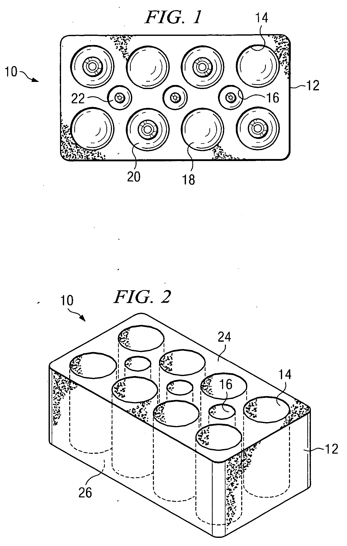
[0018] Referring to FIG. 1, there is illustrated a top plan view of a storage device 10 for light bulbs according to the present invention. A block 12 of resilient material having a density of at least 0.5 pounds per cubic foot (pcf) is shown, the block 12 having a first (top) and a second (bottom) substantially parallel sides and a plurality of cavities formed therein for receiving light bulbs within the cavities. The cavities are shaped generally to correspond to the silhouette or outline shape of the light bulb or other article intended to be stored therein. Further, the cavities are spaced to maximize the storage capacity of the storage device while providing sufficient resilient foam material therebetween for adequate cushioning in the event of impact or compression stresses exerted upon the storage device. The spacing may take advantage of the peculiar shapes of light bulbs by arranging them in alternate orientations.

[0019] The resilient material, which is preferably homogeneo...

second embodiment

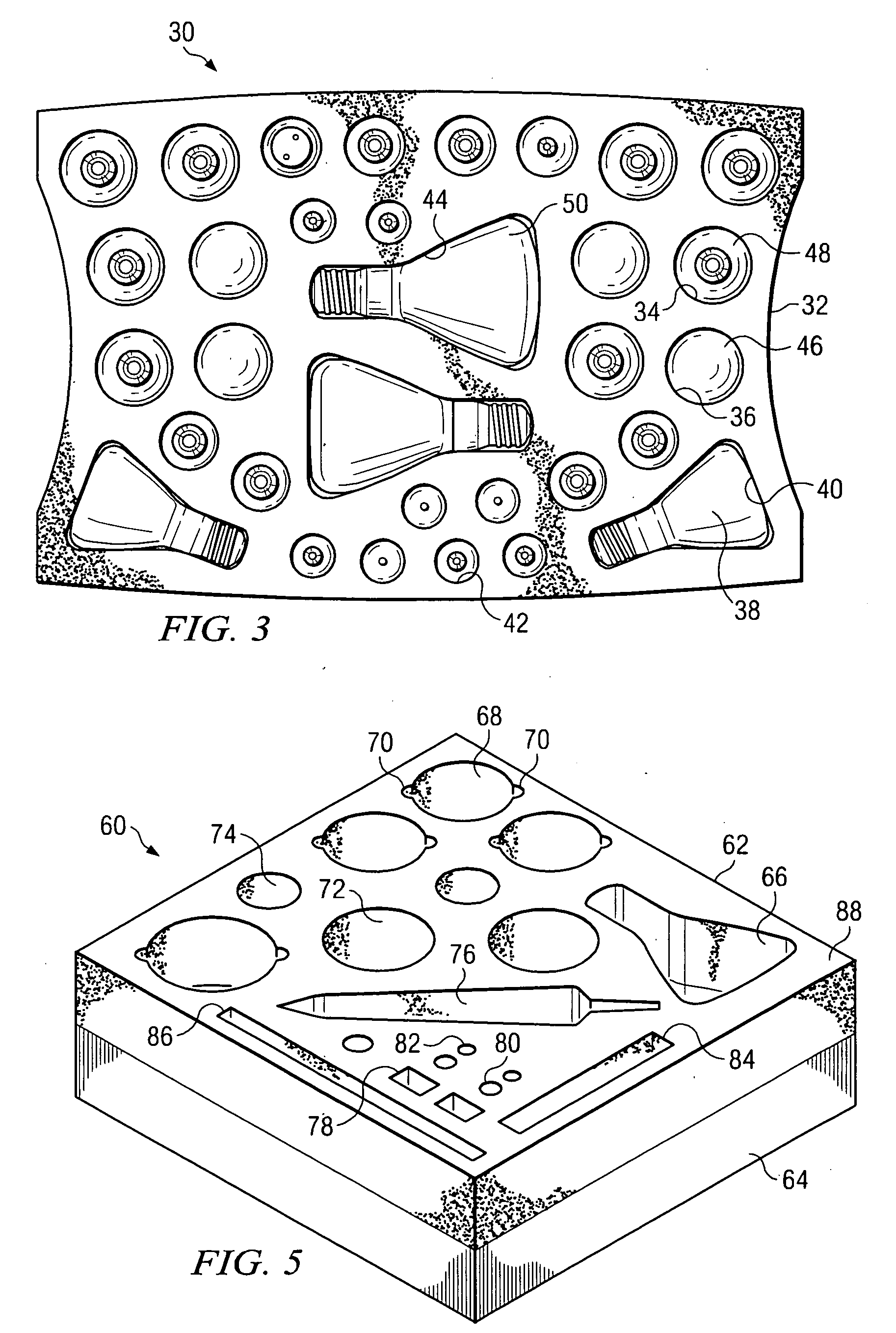
[0025] Referring to FIG. 3, there is illustrated a storage device 30 for light bulbs according to the present invention. The embodiment of FIG. 3 is constructed similarly to the embodiment of FIG. 1 except for its size, its shape, and the arrangement of and variety of light bulbs stored within its cavities. As mentioned in the description for FIG. 1, the first side 54 (see FIG. 4) and second side 56 (see FIG. 4) are generally parallel to each other and will be spaced apart by a predetermined distance that is at least the same as or slightly greater than the largest dimension or diameter of the bulbs to be stored therein. The foam block 32 is also larger to accommodate more bulbs. The foam block 32 may be shaped to fit within a storage container (not shown). When used, a storage container (not shown, but see, e.g., FIG. 7) may be constructed of a transparent material for inspection of the contents without opening the container.

[0026] The cavities in the storage device 30 shown in FIG...

third embodiment

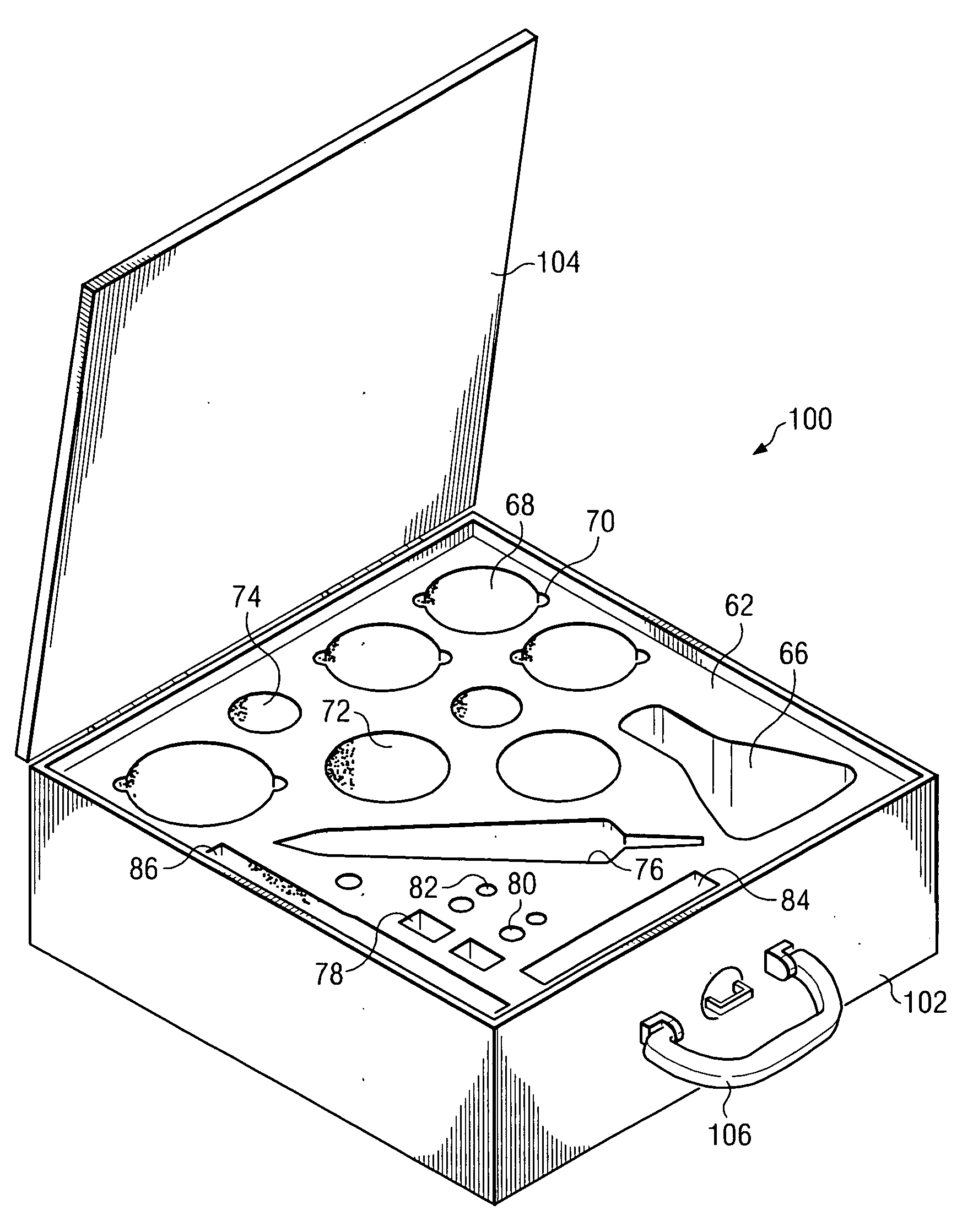
[0028]FIG. 5 illustrates a storage device 60 for light bulbs and associated supply articles for maintaining a residential or office habitation according to the present invention. The storage device 60 of FIG. 5 is constructed of a first layer 62 and a second layer 64. The first layer is preferably fabricated from polyurethane (PU) foam, e.g., by die cutting or other process well known in the art. Cavities of various sizes and shapes to accommodate light bulbs and other articles are provided. The PU foam should have a density of at least 0.5 pcf and preferably in the range of 0.8 pcf to 1.5 pcf. The second layer 64 may be fabricated of PU or other materials such as expanded polystyrene (EPS) foam. EPS foam is a light weight material that is also rigid; that is, it lacks the same property of resilience that is found in the PU foam material. Thus, the EPS material may be utilized as a base or floor of a storage system, as will be described. The density of the EPS used in the second lay...


PUM


Abstract

An apparatus for storing light bulbs and other articles for maintaining an office or residence habitation, comprising one or more layers of low density material. A plurality of cavities are formed in at least a first layer, each cavity shaped to conform to and retain therewithin the light bulb or other maintenance article.

Description

CROSS REFERENCE TO RELATED APPLICATIONS [0001] The present application claims priority to the Provisional U.S. Patent Application Ser. No. 60 / 683,762 filed May 23, 2005 by the same inventors and entitled STORAGE DEVICE FOR LIGHT BULBS.BACKGROUND OF THE INVENTION [0002] 1. Field of the Invention [0003] The present invention generally relates to packaging devices and, more particularly, to protective devices for storing glass or other fragile items such as light bulbs. The device may also be configured for storing other supply articles used in the routine maintenance of residential or office habitation. [0004] 2. Description of the Prior Art [0005] Packaging devices are readily available for storing nearly all kinds of glassware and other fragile glassware items. Some examples of the types of items stored in protective packaging devices include glassware, dishware, crystal ware, vases, art glass, ornaments, figurines, and the like. Such packaging is especially required for storing or ...

Claims


Application Information

Patent Timeline
Patent Type & Authority Applications(United States)
IPC IPC(8): B65D85/42
CPCB65D85/42B65D81/113
Inventor LAKE, RUSSELL D.MARCANTONIO, GIANDOMENICO
Owner TIZIOS
Learn More